
Binding machine with tape

a technology of binding machine and tape, which is applied in the field of binding machine with tape, can solve the problems of high cost of tape roll, inability to satisfactorily fracture the tape wound around the railroad box lunch, and the like, and achieves the effect of low binding cost and easy fracture of binding tap

Inactive Publication Date: 2005-06-07
HATAYA HIROSHI
View PDF11 Cites 4 Cited by
  • Summary
  • Abstract
  • Description
  • Claims
  • Application Information

AI Technical Summary

Benefits of technology

[0012]An object of the present invention is to provide a binding machine with a tape, in which a user can easily fracture a binding tape, and the binding cost is low.
[0014]In this mode, the nick is formed in the stage of the enlarged loop before tightening, and the tape is then tightened to contract the loop, thereby binding the material to be bound. It is possible to use as the tape in the tape roll a conventional one having no nick. Therefore, the binding cost can be made low through the reduction in the cost of the tape.

Problems solved by technology

However, a person who will eat the railroad box lunch or the like can not, in some cases, satisfactorily fracture the tape wound around the railroad box lunch or the like.
Therefore, an enormous number of nicks are previously formed with very small spacing at a side edge of the material itself of the tape wound around the tape roll.
However, such a tape roll is higher in cost by approximately 30%, for example.
Therefore, the binding cost is increased.

Method used


Image

  • Binding machine with tape
  • Binding machine with tape
  • Binding machine with tape

Examples


Embodiment Construction

[0022]A preferred embodiment of the present invention will be described while referring to the accompanying drawings.

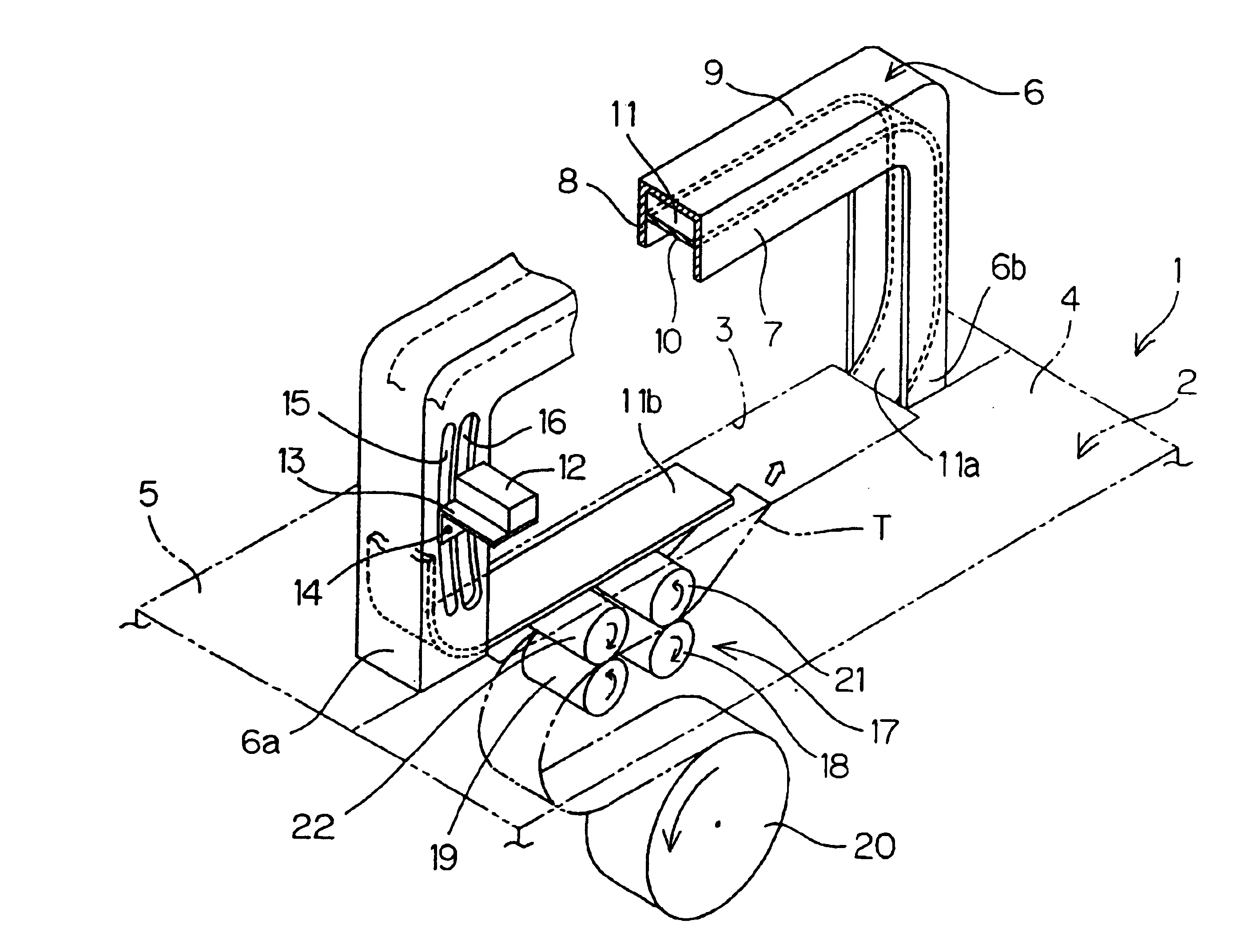
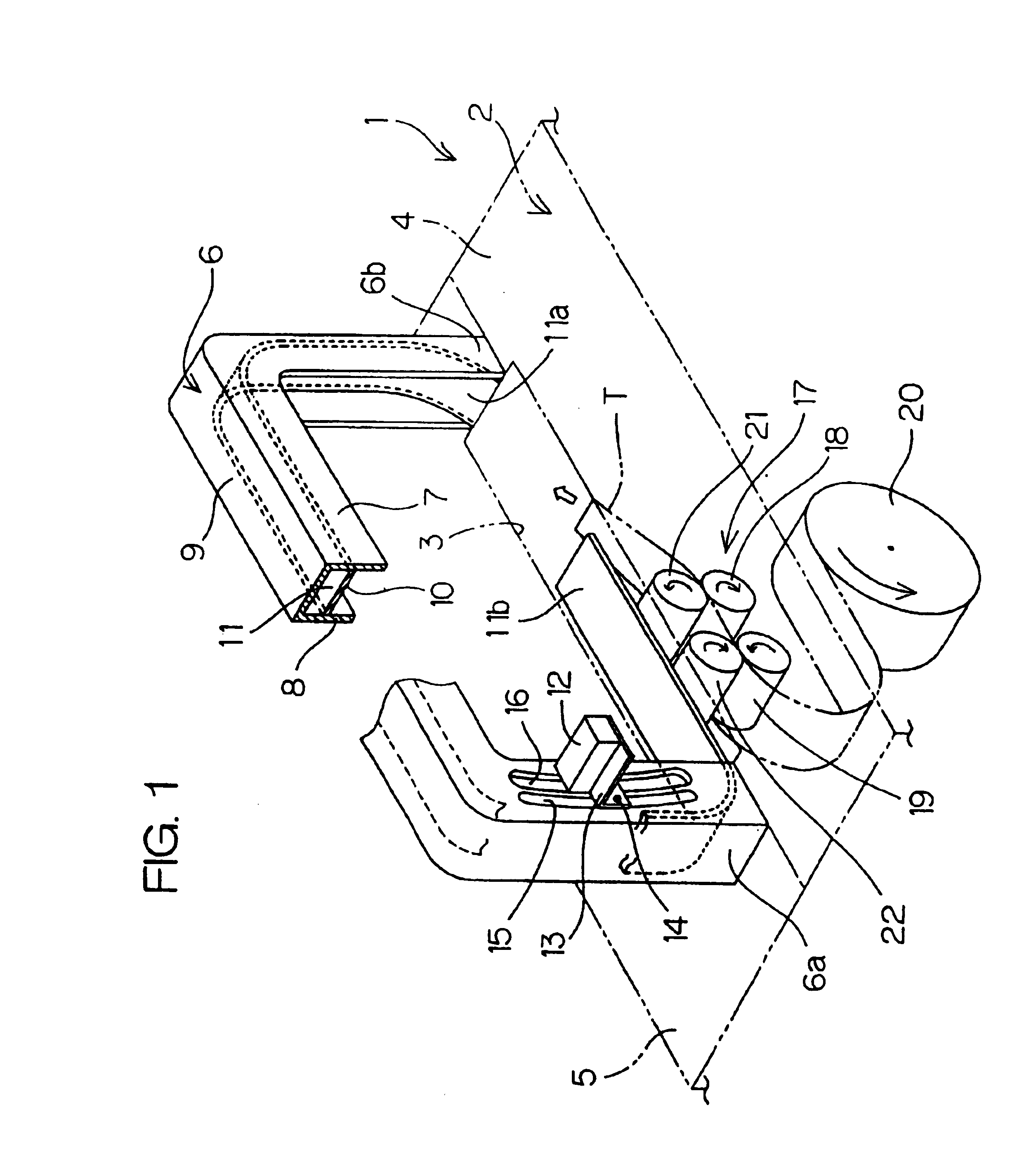
[0023]FIG. 1 illustrates a principal part of a binding machine with a tape according to an embodiment of the present invention. Referring to FIG. 1, an upper surface of the main body of a binding machine 1 is formed by a table 2 for receiving a material to be bound. The table 2 is divided into a front table 4 and a rear table 5 with a groove 3 serving as a tape path interposed therebetween. Legs 6a and 6b of a guide frame 6 in an arch shape arranged above the table 2 are respectively fixed to both ends of the groove 3. The guide frame 6 has a shape (a so-called groove shape) in cross section having a pair of flanges 7 and 8 and a web 9 connecting the flanges 7 and 8 to each other. A front sidewall and a rear sidewall of a guide path 10 are respectively composed of the pair of flanges 7 and 8.

[0024]Furthermore, a guiding member 11 composed of an arch-shaped plate, for...


PUM


Abstract

A binding machine with a tape enlarges a loop formed at an end of a tape to a predetermined size by the travel of the tape. The loop enlarged to the predetermined size is contracted, to bind a material to be bound in the loop. The binding machine comprises nick formation means for forming a nick for inducing fracture at a side edge of the tape having the loop enlarged to the predetermined size.

Description

CROSS REFERENCE TO RELATED APPLICATION[0001]This application claims priority benefits under 35 USC § 119 of Japanese Patent Application Serial No. 2001-206693, the disclosure of which is incorporated by reference.BACKGROUND OF THE INVENTION[0002]1. Field of the Invention[0003]The present invention relates to a binding machine with a tape, in which a loop is formed by the tape, and the loop is tightened, to bind a material to be bound.[0004]2. Description of Related Arts[0005]Conventionally provided as a small-sized binding machine for binding bills or the like is one for winding a binding tape. At least one surface of the binding tape has thermal adhesive properties. The binding tape is wound around a material to be bound, and an outer surface of its winding start portion and an inner surface of its winding end portion are overlapped with each other. A heater / presser heated by a heater is pressed against an overlapped portion. The overlapped portion is heated and bonded by thermopla...

Claims


Application Information

Patent Timeline
Patent Type & Authority Patents(United States)
IPC IPC(8): B65B13/02B65B13/06B65B13/08B65B13/18B65B61/02
CPCB65B13/18B65B61/02Y10S412/902B65B13/02
Inventor HATAYA, HIROSHI
Owner HATAYA HIROSHI
Learn More