
Touch display device and touch device

a display device and touch technology, applied in the field of touch display devices, can solve the problems of still having some drawbacks to overcom

Inactive Publication Date: 2015-05-07
INTERFACE OPTOELECTRONICS SHENZHEN +1
View PDF11 Cites 2 Cited by
  • Summary
  • Abstract
  • Description
  • Claims
  • Application Information

AI Technical Summary

Benefits of technology

[0028]To sum up, the dummy structure disposed in the touch device is provided in the embodiments of the present invention. When comparing the touch devices of the present invention and conventional touch devices under an equal mechanical strength, due to the thinned thickness of the cover, the touch devices of the present invention can provide better touch sensitivity without lowering the entire mechanical strength of the touch devices. In this way, the touch devices may have robust mechanical strength and may not be fractured easily during the corresponding adhesion process or operation.

Problems solved by technology

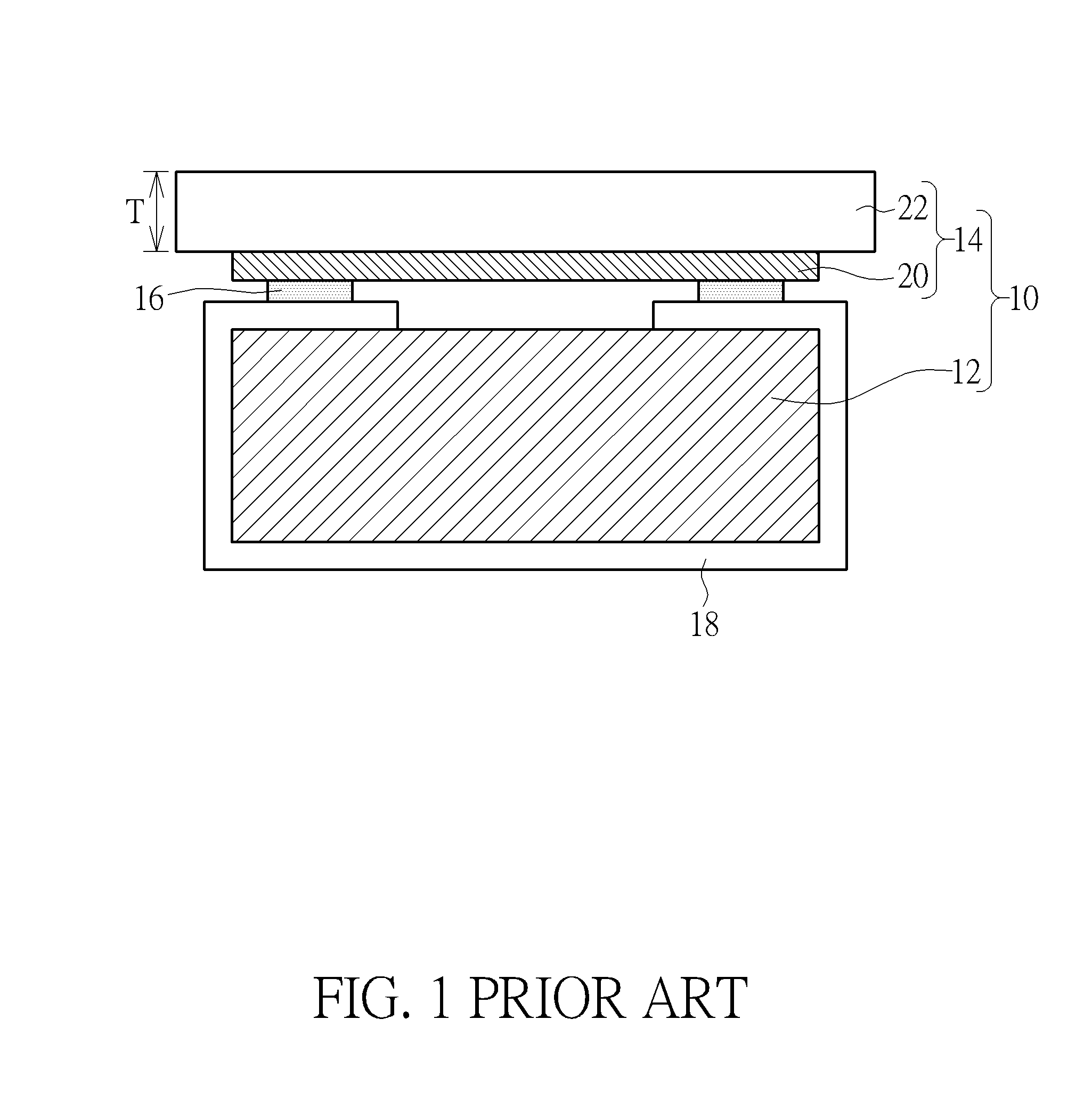
Although the above-mentioned device is widely used in large-size out-cell touch display devices, it still has some drawbacks needing to be overcome.

Method used


Image

  • Touch display device and touch device
  • Touch display device and touch device
  • Touch display device and touch device

Examples


first embodiment

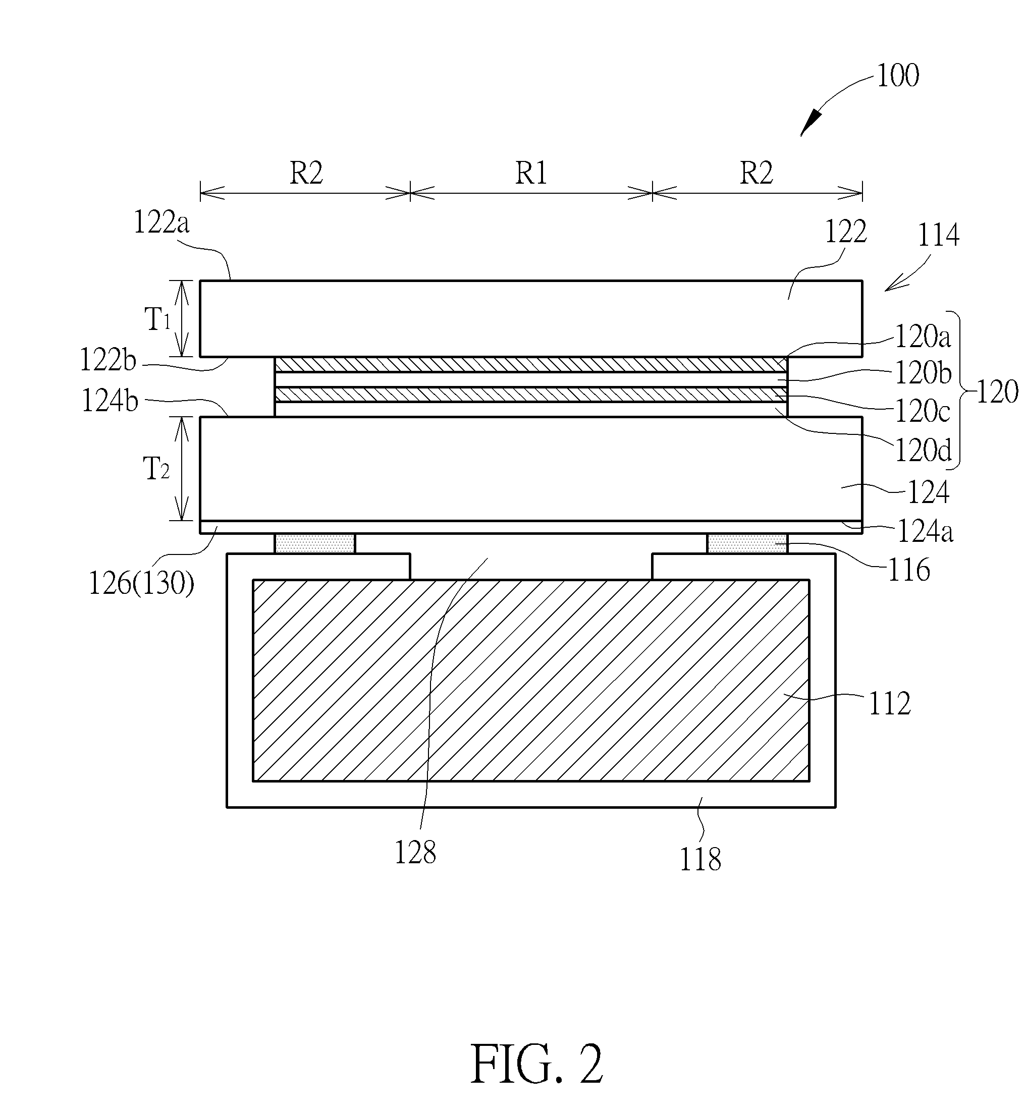
[0018]FIG. 2 is a schematic cross-sectional diagram showing a touch display device in accordance with the present invention. A touch display device 100 shown in FIG. 2 includes a viewing region R1 and a peripheral region R2. The peripheral region R2 is on at least one side of the viewing region R1 and preferably surrounding the periphery of the viewing region R1. The viewing region R1 is a region for display images, while the peripheral region R2 is a region for outer trace lines. The touch display device 100 includes a display device 112 and a touch device 114, which may be used to provide images and touch sensing function respectively. These two devices are preferably independently fabricated and then combined with each other through an adhesion layer 116, such as an annular adhesive or functional adhesive. Also, a frame 118 may be disposed around the periphery of the display device 112 so that the touch device 114 may be fixed to the display device 112 by adhering it to the frame...

second embodiment

[0025]The following description details a touch display device and a touch display device according to the present invention. To simplify the description, the following description will detail the dissimilarities among those embodiments and the variant embodiments, and the identical features will not be redundantly described. For the sake of brevity and clarity, the identical components in each of the following embodiments are marked with identical symbols.

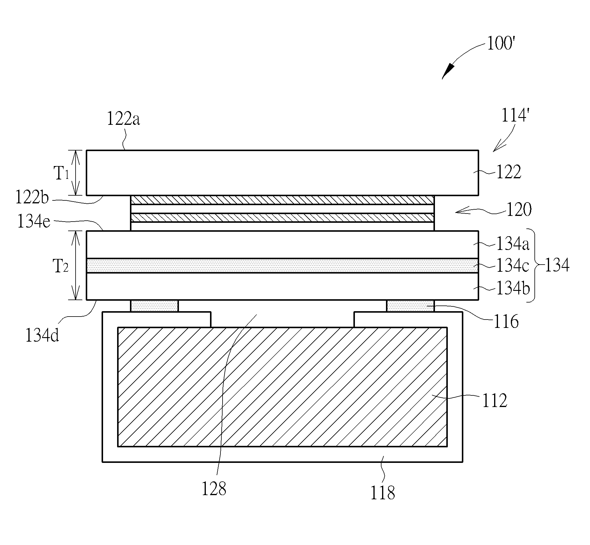
[0026]FIG. 5 is a schematic cross-sectional diagram showing a touch display device in accordance with a second embodiment of the present invention. One difference between the present embodiment and the first embodiment is that a dummy structure 134 of a touch display device 100′ includes at least two dummy substrates 134a and 134b and an adhesion layer 134c. The adhesion layer 134c is blanketly disposed between the dummy substrates 134a and 134b so as to integrate the dummy substrates 134a and 134b. The adhesion layer 134c may be ...


PUM


Abstract

A touch display device includes a display device and a touch device disposed on the display device. The touch device includes a cover, a dummy structure and a touch sensing element. The touch sensing element is disposed between the cover and the dummy structure in a way that one surface of the touch sensing element is completely covered by the dummy structure.

Description

BACKGROUND OF THE INVENTION[0001]1. Field of the Invention[0002]The present invention relates generally to the field of touch devices, and more particularly to touch display devices with out-cell touch devices and out-cell touch devices.[0003]2. Description of the Prior Art[0004]Touch panels have been widely used in various external input devices of electronic equipment. In recent years, with the flourishing development of the consumer electronics, there are many display devices in combination with touch sensing functions, such as mobile phones, GPS navigator system, tablet PCs, personal digital assistants (PDA), and laptop PC. In these consumer electronics, out-cell touch panels, in which touch panels are adhered to display panels, are widely used in current global touch panel industry.[0005]FIG. 1 is a cross-sectional diagram showing a conventional touch display device. A touch display device 10 includes at least a display device 12, a touch device 14 and an adhesion layer 16. The...

Claims


Application Information

Patent Timeline
Patent Type & Authority Applications(United States)
IPC IPC(8): G06F3/041G06F1/16
CPCG06F1/1643G06F3/0412G06F1/1637G06F3/0443G06F3/0445G06F3/0446
Inventor HUANG, CHEN-HSINGTSAI, YING-HUNGSHIE, DE-CHING
Owner INTERFACE OPTOELECTRONICS SHENZHEN
Learn More