
Disk carrier

Inactive Publication Date: 2005-06-07
ENTEGRIS INC
View PDF9 Cites 25 Cited by
  • Summary
  • Abstract
  • Description
  • Claims
  • Application Information

AI Technical Summary

Benefits of technology

[0013]In operation, the first embodiment is used by providing a disk carrier including a disk cassette having an open top, an open bottom, and at least one end wall ingress; a top cover including at least one flap having an articulation defining a lower flap portion; a bottom cover; and at least one disk. The at least one disk is inserted into the disk cassette and the bottom cover is attached to the disk cassette. The top cover is attached to the disk cassette, causing the lower flap portion to ride over a connecting structure on the disk cassette or bottom cover to at least partially connect the flap to the disk cassette and bottom cover. The flap is then pushed inwardly to secure the connection. Those skilled in the art are aware that these steps may be performed as effectively in other orders as well.

Problems solved by technology

Second, the top covers have flaps that come over the side walls of the disk cassette and attach to the side walls just below the U-shaped contours.
This attachment means is a source or cause for increased particulation on the end disks housed in a disk carrier, which is undesirable in a clean room manufacturing process.

Method used


Image

  • Disk carrier
  • Disk carrier
  • Disk carrier

Examples


first embodiment

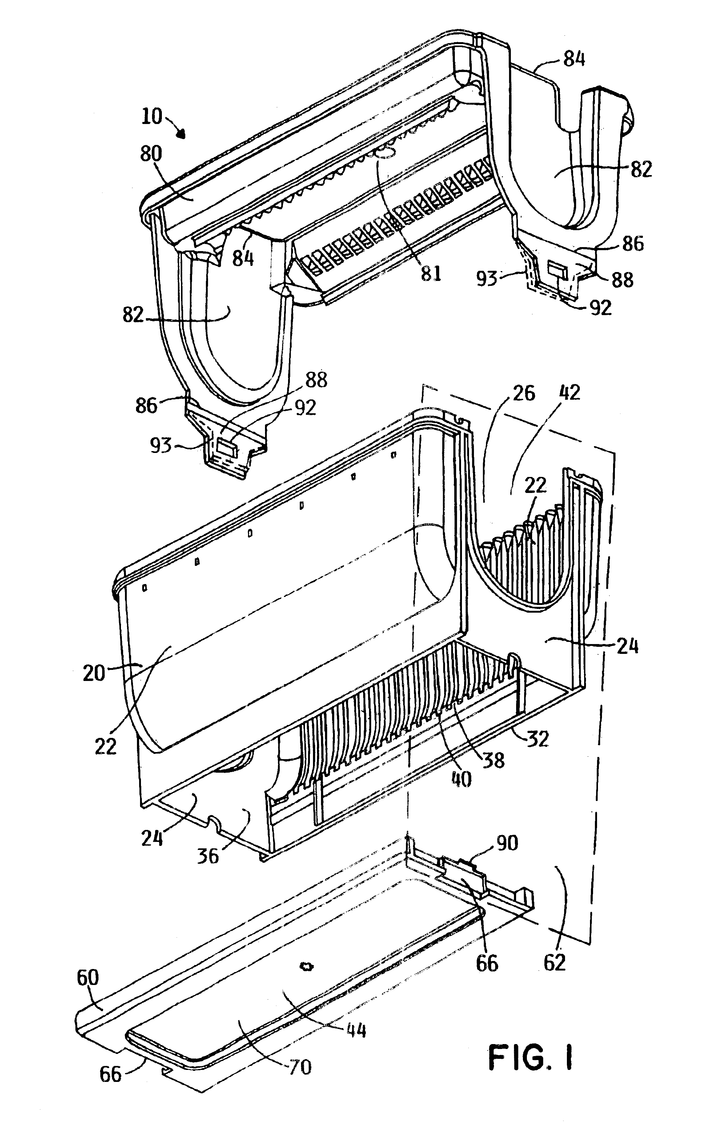
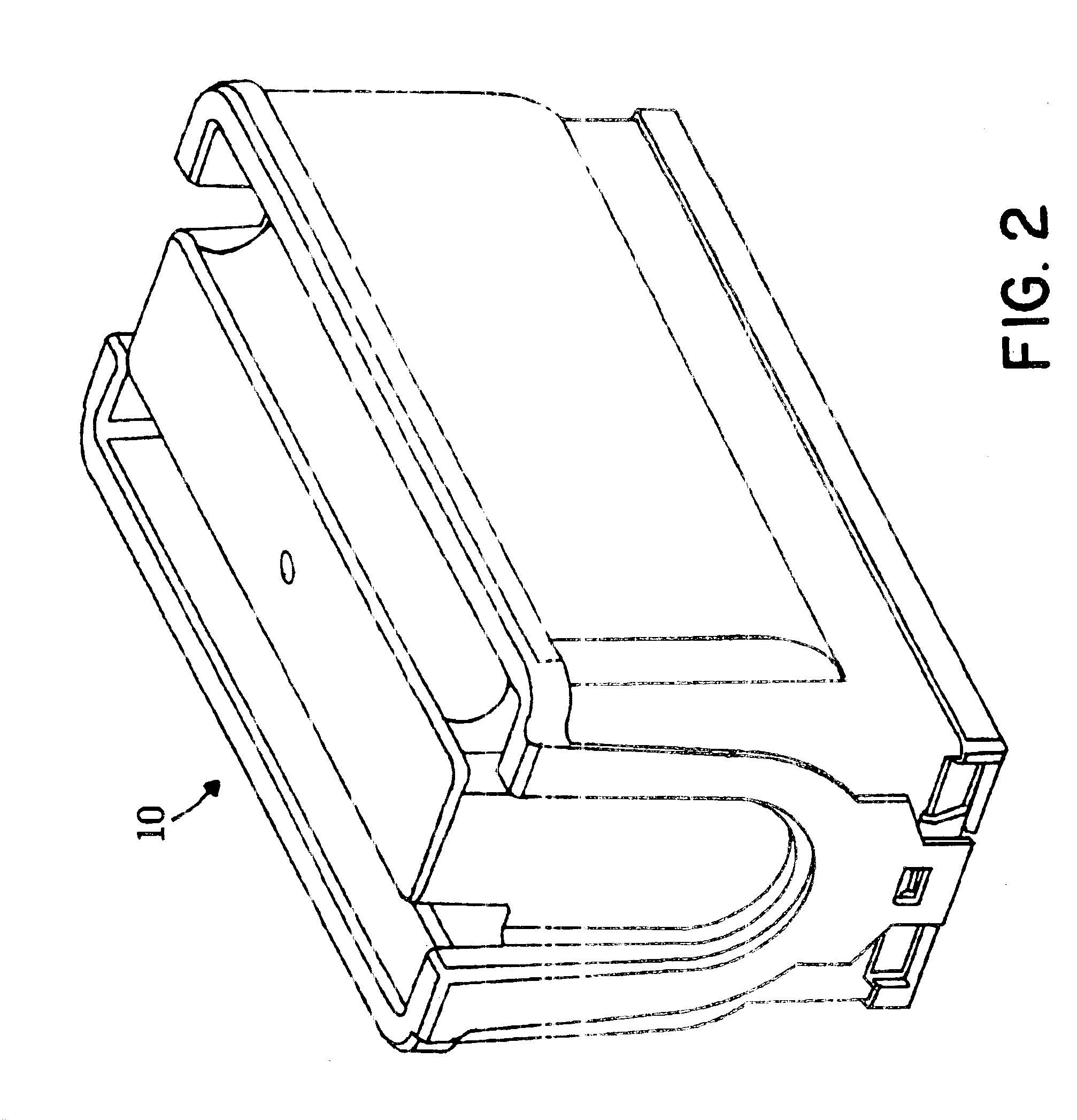
[0030]The preferred embodiment relates to a disk carrier in accordance with the present invention. As shown in FIGS. 1-7, the disk carrier 10 comprises a disk cassette 20, a bottom cover 60, and a top cover 80. The disk cassette 20 has two opposing side walls 22 and two opposing end walls 24 forming an interior 26 to enclose and house a plurality of disks (not shown) therein, a top edge 28 defining a top opening 30, and a bottom edge 32 defining a bottom opening 36. The side walls 22 have a plurality of disk confining ribs 38 and a plurality of slot portions 40 to secure the disks in the interior 26 of the disk cassette. An industry standard is to house 25 disks. The end walls each have an ingress or U-shaped contoured top 42 to access the disks. The bottom cover 60 has two bottom cover ends 66 and is configured and arranged to align with and attach to the bottom edge 32 to cover the bottom opening 36. The bottom cover 60 may also have a living hinge 68. Together, the end walls 24 a...

second embodiment

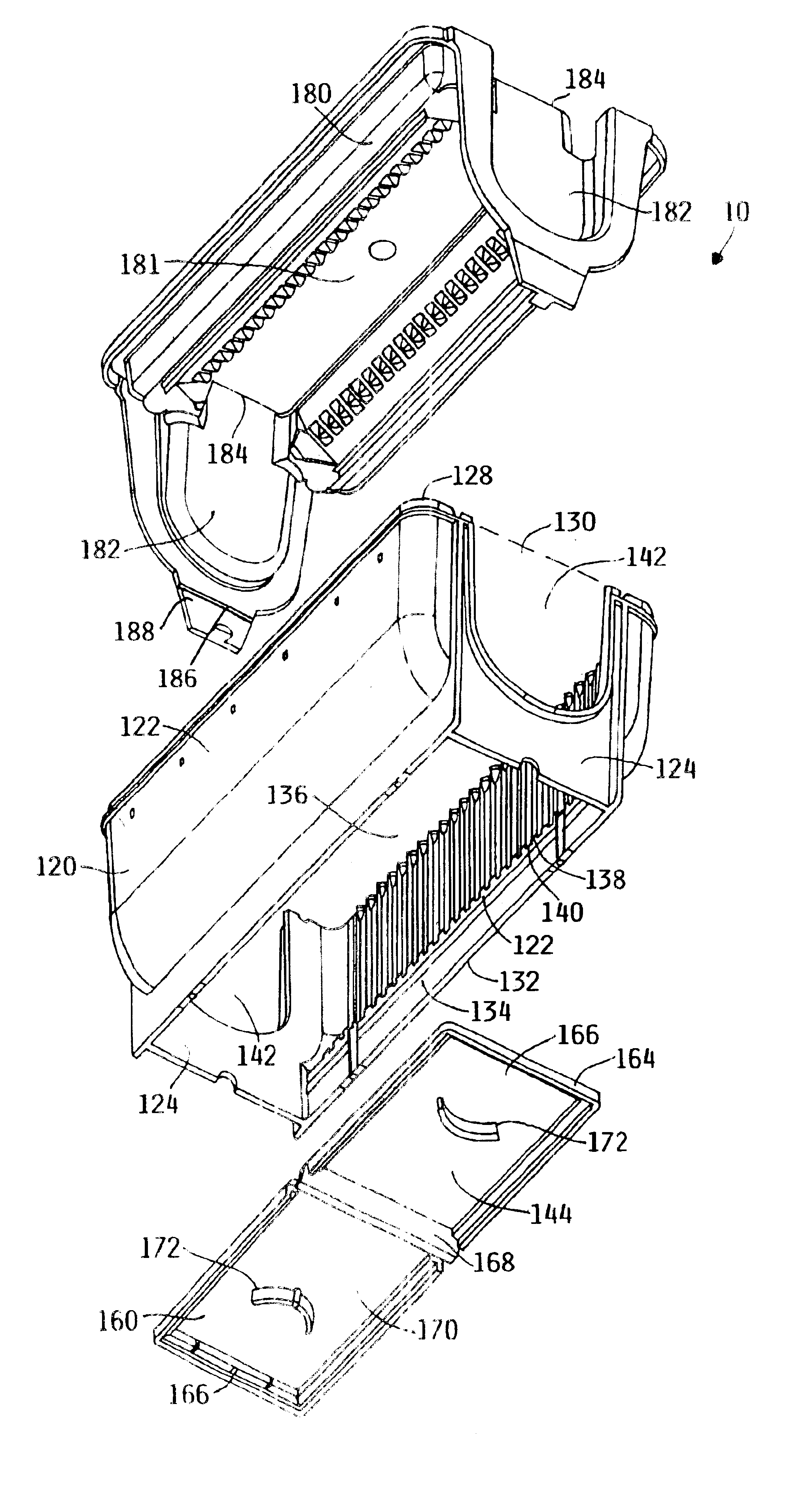
[0032]the disk carrier 10, as shown in FIGS. 9-15, also comprises a disk cassette 120, a bottom cover 160, and a top cover 180. The disk cassette 120 has two opposing side walls 122 and two opposing end walls 124 forming an interior 126 to enclose and house a plurality of disks (not shown) therein, a top edge 128 defining a top opening 130, and a bottom edge 132 having an inner perimeter 134 and defining a bottom opening 136. The side walls 122 have a plurality of disk confining ribs 138 and a plurality of slot portions 140 to secure the disks in the interior 126 of the disk cassette 120. The end walls 124 each have an ingress or U-shaped contoured top 142 to access the disks. The bottom cover 160 has a bottom cover edge 164, two bottom cover ends 166, and a living hinge 168 between the bottom cover ends 166 to contract and expand the bottom cover 160. The bottom cover has finger grips 172 to perform this task manually, if necessary. The bottom cover 160 is configured and arranged t...


PUM

PropertyMeasurementUnit
electrically conductiveaaaaaaaaaa
perimeteraaaaaaaaaa
cooperating connection structureaaaaaaaaaa

Abstract

The disk carrier is used to house and secure a plurality of disks and comprises a disk cassette having an open top, an open bottom, and end wall ingresses; a top cover; and a bottom cover. The top cover has flaps to cover the end wall ingresses. To reduce particulation from opening and closing the disk carrier, one embodiment of the disk carrier implements an articulation in the flaps. Another embodiment implements a living hinge on the bottom cover. The disk carrier also has a path to ground for dissipating static and other electrical charge away from the disks.

Description

RELATED APPLICATIONS[0001]This application claims the benefit of U.S. Provisional Application No. 60 / 309,241, filed on Jul. 31, 2001, which is hereby incorporated herein by reference.FIELD OF THE INVENTION[0002]The present invention relates to a container configured to hold a particular article or set of articles or material. In particular, the present invention relates to a disk carrier or container used to house and protect computer components such as magnetic disks or wafer disks during a manufacturing or transportation process, wherein the disk carrier comprises a disk cassette, a top cover, and a bottom cover, the top cover having an articulation in one embodiment and the bottom cover having a living hinge in another embodiment.BACKGROUND OF THE INVENTION[0003]As precision and smaller tolerances become the expected norm in computational and processing machines, better equipment used to fabricate components is expected by manufacturers. To house and protect magnetic disks, wafer...

Claims


Application Information

Patent Timeline
Patent Type & Authority Patents(United States)
IPC IPC(8): G11B33/14G11B33/04H01L21/673H01L21/67B65D85/86
CPCG11B33/0444H01L21/67386H01L21/67363G11B33/1493
Inventor WHALEN, THOMAS J.ADAMS, MICHAEL S.ANDERSON, GARRY
Owner ENTEGRIS INC
Learn More