
Method and apparatus for electromagnetic drying of printed media

a technology of electromagnetic drying and printed media, applied in lighting and heating apparatus, electric/magnetic/electromagnetic heating, furnaces, etc., can solve the problems of operator waiting a long time, safety and scorching hazards being introduced, safety and scorching hazards being active, etc., to reduce leakage of electromagnetic radiation, attenuate microwave signals, and promote absorption of electromagnetic radiation

Inactive Publication Date: 2005-06-07
RICOH KK
View PDF40 Cites 22 Cited by
  • Summary
  • Abstract
  • Description
  • Claims
  • Application Information

AI Technical Summary

Benefits of technology

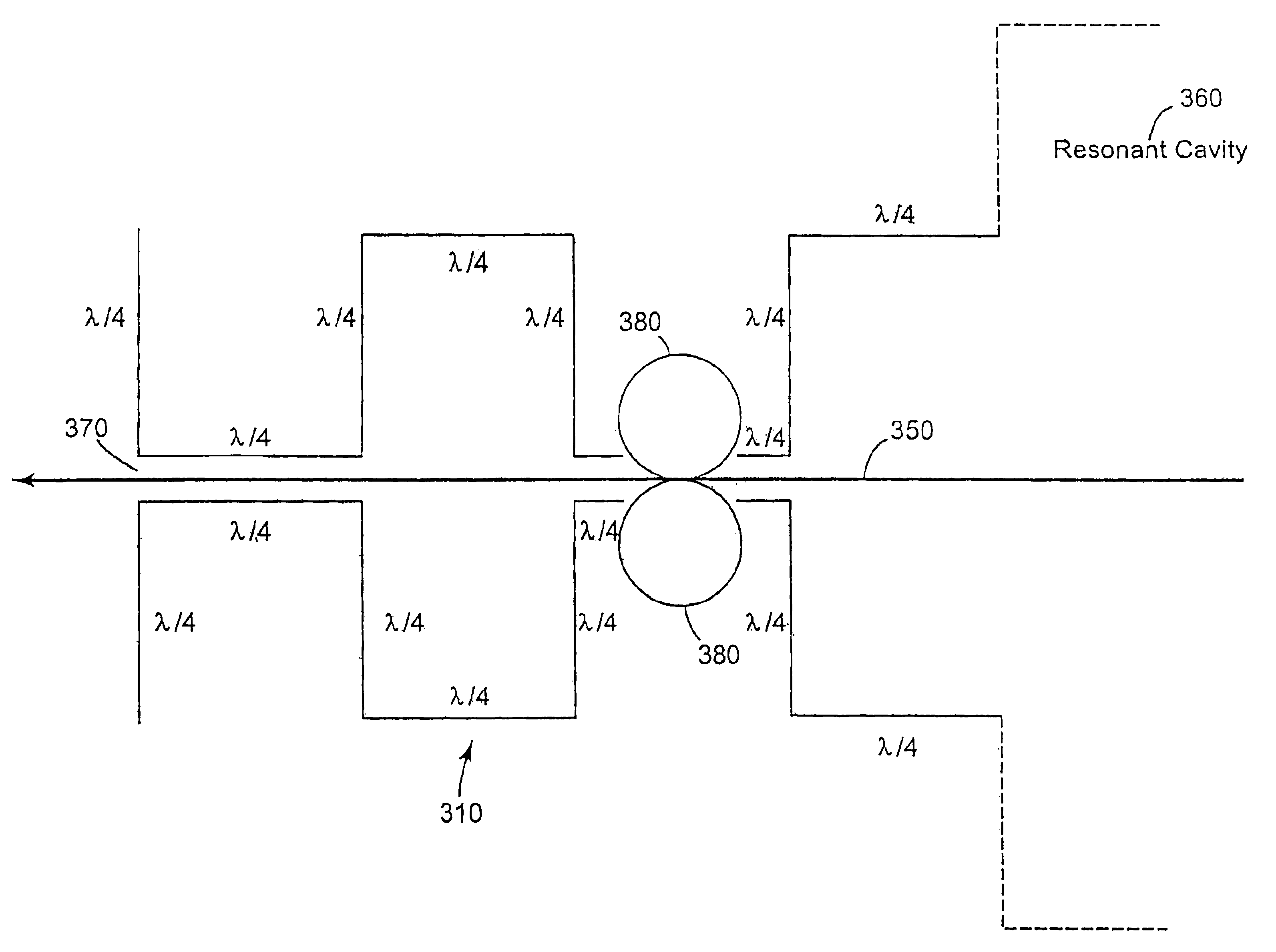
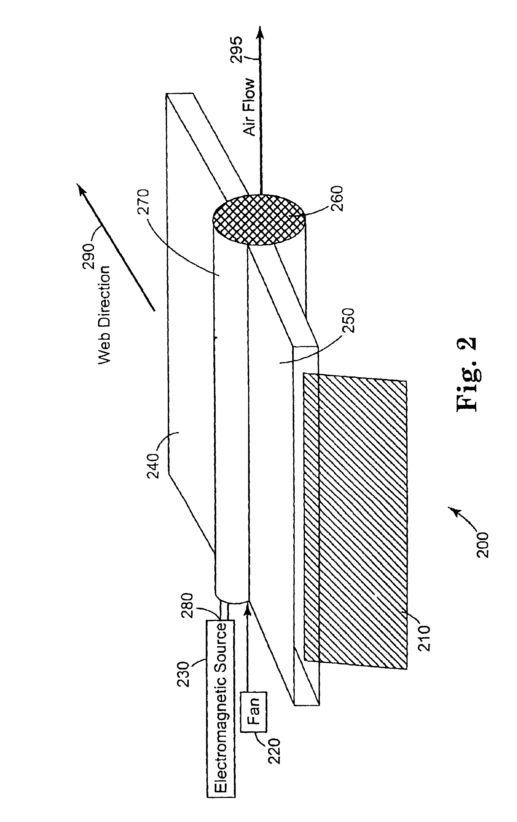
[0016]In another embodiment of the present invention a printed media drying apparatus is presented. The apparatus includes an electromagnetic drying unit to promote absorption of electromagnetic radiation by moisture particles contained within the printed media. The electromagnetic drying unit includes a chamber having a plurality of orifices coupled to receive printed media having a first moisture content and is coupled to provide the printed media having a second moisture content less than the first moisture content. The chamber substantially reduces leakage of the electromagnetic radiation throu

Problems solved by technology

In addition to the excessive power consumption problem of the heated drying unit, a safety and scorching hazard is introduced when the paper is delayed while passing through or across the heated drying unit.
Since the drying unit is slow to cool, the safety and scorching hazard may remain active for some time.
Furthermore, the operator must wait a lengthy time for the dryer to cool to avoid a bum hazard when clearing paper from the dryer.
An additional problem encountered

Method used


Image

  • Method and apparatus for electromagnetic drying of printed media
  • Method and apparatus for electromagnetic drying of printed media
  • Method and apparatus for electromagnetic drying of printed media

Examples


Embodiment Construction

[0026]In the following description of the exemplary embodiment, reference is made to the accompanying drawings that form a part hereof, and in which is shown by way of illustration the specific embodiment in which the invention may be practiced. It is to be understood that other embodiments may be utilized as structural changes may be made without departing from the scope of the present invention.

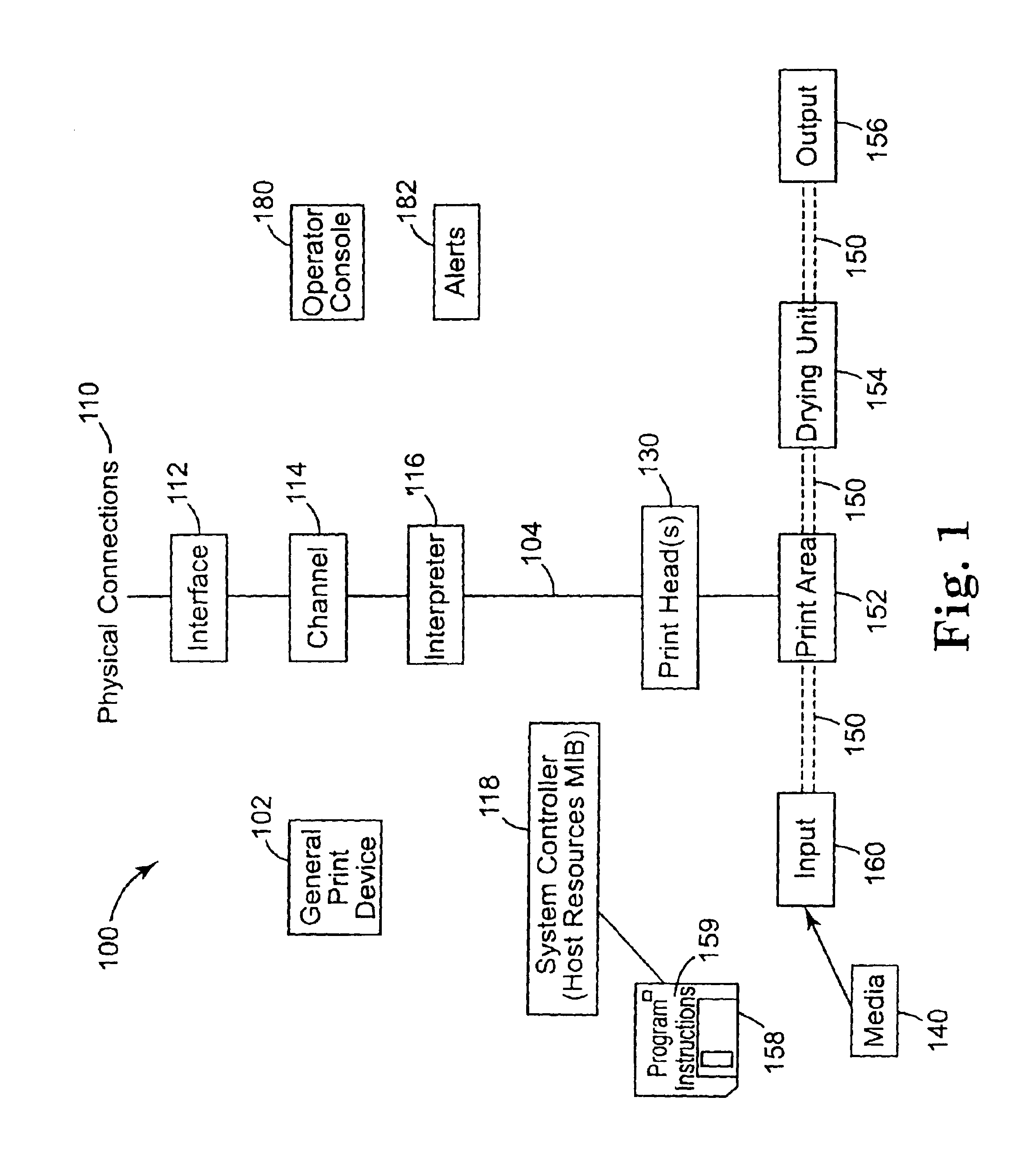
[0027]The present invention provides a method, apparatus and article of manufacture for drying printed media in a printing device using electromagnetic, e.g. microwave, radiation. The microwave heaters according to the present invention provide instant-on and instant-off heating, which reduces the warm-up time required by the microwave heater as well as reducing safety and fire concerns, when for example, the web becomes jammed within the printing device. Furthermore, microwave heaters according to the present invention allow operation at chosen frequencies, which facilitates a higher dryin...


PUM


Abstract

A method, apparatus and article of manufacture for providing electromagnetic drying of printed media. A resonant cavity allows support of standing waves along many radial axes throughout the resonant cavity. The electromagnetic drying unit allows forced air to be introduced into the resonant cavity, thereby reducing moisture within the resonant cavity and extending the life of the resonant cavity. Input and output openings may be arranged longitudinally along the resonant cavity and may be designed to substantially reduce the amount of electromagnetic radiation emanating from them during operation. A honeycomb feature at the end of the resonant cavity may allow egress of the forced air, while substantially reducing the amount of electromagnetic radiation emanating from the end of the resonant cavity.

Description

RELATED PATENT DOCUMENTS[0001]This is a divisional of patent application Ser. No. 10 / 076,985, filed on Feb. 15, 2002, to which Applicant claims priority under 35 U.S.C. §120.BACKGROUND OF THE INVENTION[0002]1. Field of the Invention[0003]This invention relates in general to print output apparatus and methods, and more particularly, to a method and apparatus for electromagnetic drying of printed media.[0004]2. Description of Related Art[0005]In electronic print devices for printing, copying and desktop publishing systems, images are usually offered in electronic form, and are then referred to as electronic images. These electronic images can be stored on magnetic disk or transported via direct links or networks to the print devices. The creation of a page results in an electronic data stream or electronic file describing the several elements of the page layout in electronic format. This electronic page layout is usually expressed in a page description language. The electronic page la...

Claims


Application Information

Patent Timeline
IPC IPC(8): B41J11/00F26B3/32F26B3/34
CPCF26B3/343B41J11/002B41J11/00216
Inventor LYLE, RUTHIE D.TRELEWICZ, JENNIFER Q.BILDSTEIN, CARL ROBERT
Owner RICOH KK
Learn More