
Step and repeat imprint lithography systems

Inactive Publication Date: 2005-05-31
CANON KK
View PDF128 Cites 305 Cited by
  • Summary
  • Abstract
  • Description
  • Claims
  • Application Information

AI Technical Summary

Benefits of technology

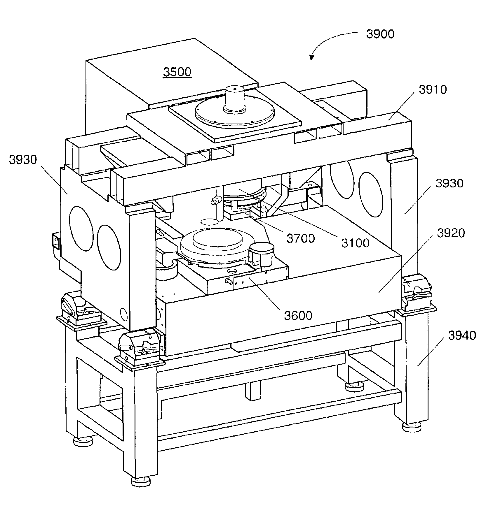
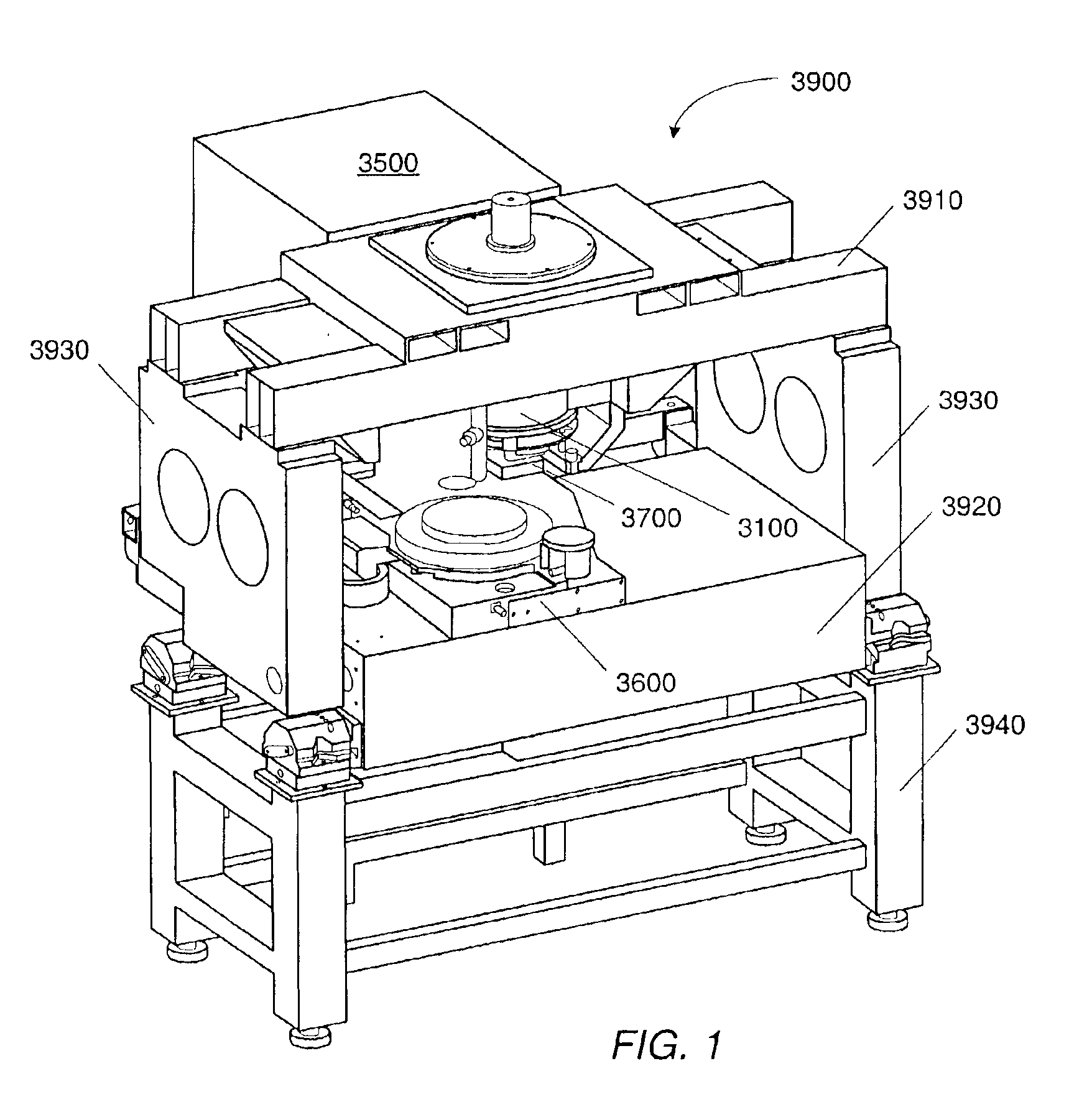
[0008]In one embodiment, a patterned layer is formed by curing a curable liquid disposed on a substrate in the presence of a patterned template. In an embodiment, a system for forming a patterned layer on a substrate includes an imprint head and a motion stage. The imprint head is configured to hold a patterned template. The imprint head also includes a fine orientation system. The fine orientation system allows motion of the patterned template with respect to a substrate to achieve a substantially parallel orientation of the patterned template. In one embodiment, the fine orientation system is a passive system that allows the template to self-correct for non-planarity when the template contacts a liquid disposed on the substrate. The imprint head further includes a force detector. The force detector i

Problems solved by technology

Expansion of the supports may contribute to errors due to misalignment of the template with the substrate.

Method used


Image

  • Step and repeat imprint lithography systems
  • Step and repeat imprint lithography systems
  • Step and repeat imprint lithography systems

Examples


Embodiment Construction

[0057]Embodiments presented herein generally relate to systems, devices, and related processes of manufacturing small devices. More specifically, embodiments presented herein relate to systems, devices, and related processes of imprint lithography. For example, these embodiments may be used for imprinting sub 100 features on a substrate, such as a semiconductor wafer. It should be understood that these embodiments may also be used to manufacture other kinds of devices including, but not limited to: patterned magnetic media for data storage, micro-optical devices, micro-electro-mechanical system, biological testing devices, chemical testing and reaction devices, and X-ray optical devices.

[0058]Imprint lithography processes have demonstrated the ability to replicate high-resolution (sub-50 nm) images on substrates using templates that contain images as topography on their surfaces. Imprint lithography may be used in patterning substrates in the manufacture of microelectronic devices, ...


PUM

PropertyMeasurementUnit
Temperatureaaaaaaaaaa

Abstract

Described are systems for patterning a substrate by imprint lithography. Imprint lithography systems include an imprint head configured to hold a template in a spaced relation to a substrate. The imprint lithography system is configured to dispense an activating light curable liquid onto a substrate or template. The system includes a light source that applies activating light to cure the activating light curable liquid.

Description

BACKGROUND OF THE INVENTION[0001]1. Field of the Invention[0002]Embodiments presented herein relate to methods and systems for imprint lithography. More particularly, embodiments relate to methods and systems for micro- and nano-imprint lithography processes.[0003]2. Description of the Relevant Art[0004]Optical lithography techniques are currently used to make most microelectronic devices. However, it is believed that these methods are reaching their limits in resolution. Sub-micron scale lithography has been a critical process in the microelectronics industry. The use of sub-micron scale lithography allows manufacturers to meet the increased demand for smaller and more densely packed electronic circuits on chips. It is expected that the microelectronics industry will pursue structures that are as small or smaller than about 50 nm. Further, there are emerging applications of nanometer scale lithography in the areas of opto-electronics and magnetic storage. For example, photonic crys...

Claims


Application Information

Patent Timeline
IPC IPC(8): B29C35/08B29C59/02G03F7/00H01L21/02H01L21/027
CPCB29C35/0888B29C59/022B82Y10/00B82Y40/00G03F7/0002B81C1/0046B29C2035/0827B29C2059/023H01L21/0271
Inventor SREENIVASAN, SIDLGATA V.WATTS, MICHAEL P. C.CHOI, BYUNG JINMEISSL, MARIO J.SCHUMAKER, NORMAN E.VOISIN, RONALD D.
Owner CANON KK
Learn More