
Fastener with gear assembly

Inactive Publication Date: 2005-05-31
MURPHY RAYMOND J
View PDF3 Cites 15 Cited by
  • Summary
  • Abstract
  • Description
  • Claims
  • Application Information

AI Technical Summary

Benefits of technology

[0013]An advantage of the present invention is a fastener which can switch between a standard driving speed and a high driving speed.
[0014]Another advantage of the present invention is a switch and gear assembly that rotates the shaft faster than the handle to apply significantly more revolutions of the shaft as compared to the revolutions necessary to the handle.
[0015]Another advantage of the present invention is reducing fatigue and stress to the user.

Problems solved by technology

This direct relationship results in fatigue and stress on the user's arm and wrists since each handle revolution results in only one revolution of the bit.
Further, typical screwdrivers enhance the fatigue and stress in tight and / or difficult work areas having obstacles between the user and the work area.
With the direct revolution ratio, this maneuvering increases the time to complete the fastening process leading to increased fatigue and stress.
The prior art does not satisfy the needs and solutions required.

Method used


Image

  • Fastener with gear assembly
  • Fastener with gear assembly
  • Fastener with gear assembly

Examples


Embodiment Construction

[0016]As stated, the present invention relates to a fastener. In particular, the present invention relates to a fastener having a gear assembly which changes to increase the speed while reducing the torque to a connector being acted upon. The gear assembly of the fastener also changes to decrease the speed while increasing the torque force to the connector.

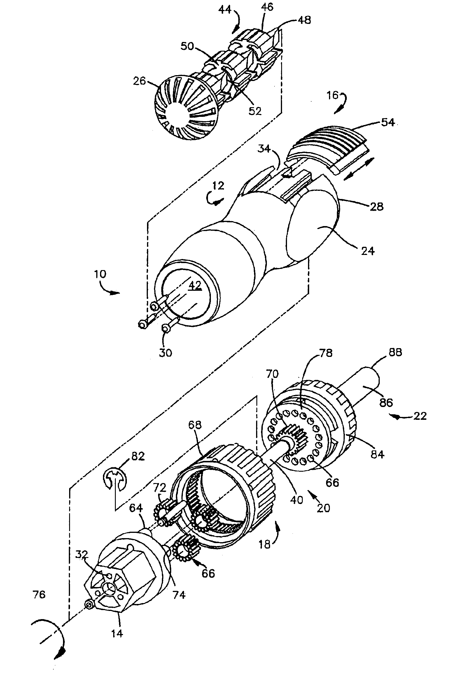
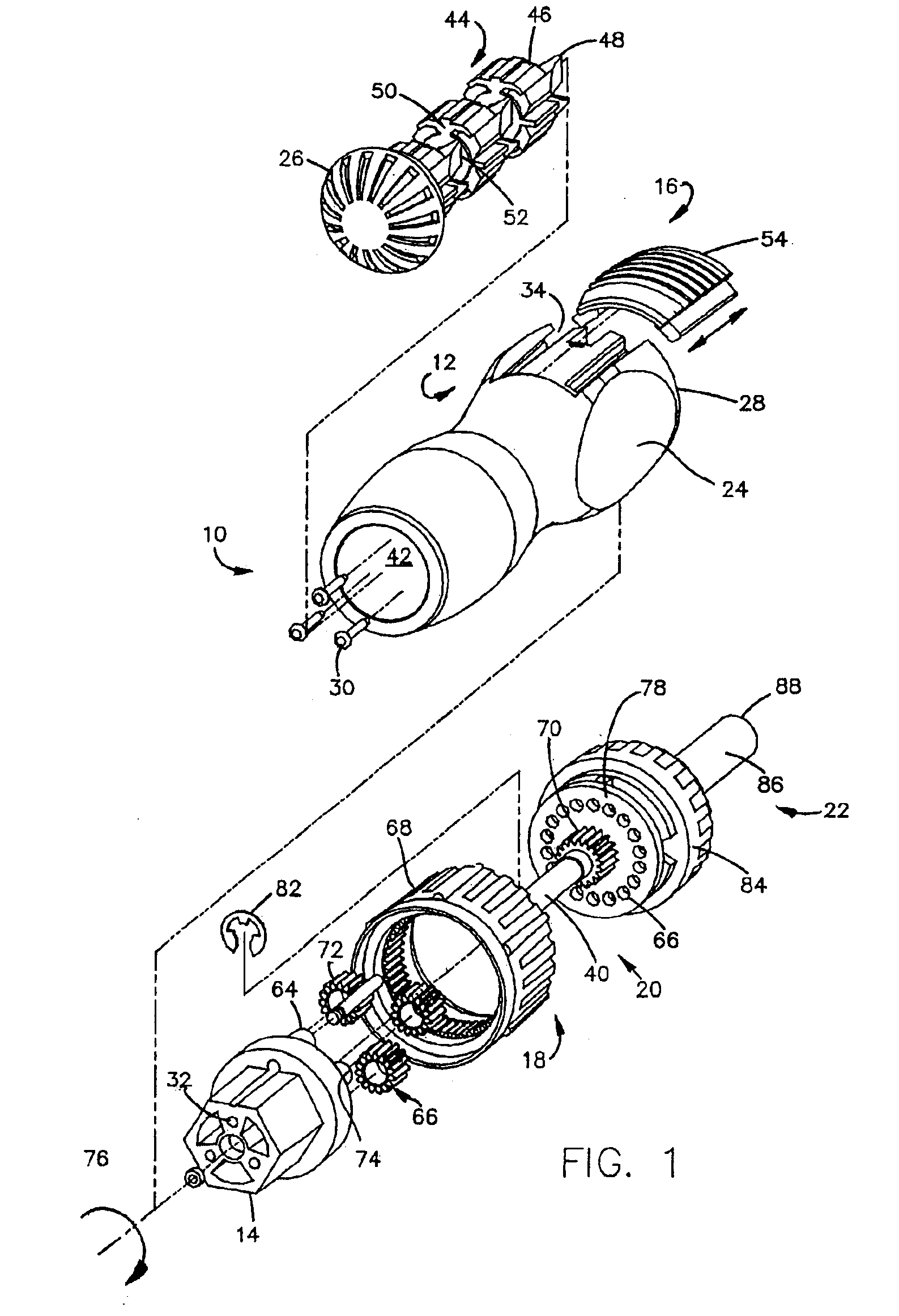
[0017]FIG. 1 illustrates a perspective breakaway view of an exemplary fastener tool generally shown as 10. The tool 10 comprises a handle assembly generally shown as 12, an insert 14, a switch assembly generally shown as 16, a gear assembly generally shown as 18, a plate assembly generally shown as 20 and a shaft assembly generally shown as 22.

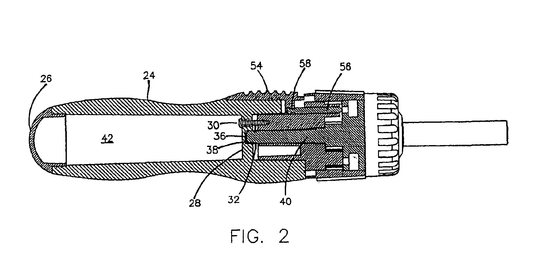
[0018]The handle assembly 12 comprises a handle 24 having an end 26 and a cut out or opening 28. The handle 24, made from a chemically resistant material, ergonomically fits comfortably in the user's hands. The opening 28 is sized and shaped to mate with the insert 14 wherein a fastener 30, ...


PUM


Abstract

A fastener with a reduced gear affect. The fastener of the present invention comprises a handle assembly having an end and an opening wherein a shaft assembly is positioned within the opening and extending from the opening. The fastener further comprises a switch assembly positioned between the handle assembly and the shaft assembly wherein the switch assembly reciprocates between a locked position and an unlocked position to control a ratio of revolutions between the handle assembly and the shaft assembly. A method of fastening comprising connecting a shaft assembly to a handle assembly and moving a switching assembly, connected to the handle assembly, to an unlocked position. Next, a gear assembly is connected to the switch assembly which engages the gear assembly to the handle assembly to increase a ratio of revolutions of the shaft assembly as compared to the handle assembly.

Description

REFERENCE TO PRIORITY DOCUMENT[0001]The present invention claims priority, to the extent permitted by law, to U.S. Provisional Application No. 60 / 402,284 filed on Aug. 9, 2002.BACKGROUND OF THE INVENTION[0002]The present invention relates to a fastener. In particular, the present invention relates to a fastener, such as a screwdriver, having a switch assembly and gear assembly which can change from a standard driving speed application to a high diving speed application.[0003]Traditional hand held screwdrivers maintain a direct relationship between the revolutions of the handle and the revolutions of the output shaft. This direct relationship results in fatigue and stress on the user's arm and wrists since each handle revolution results in only one revolution of the bit. Accordingly, the typical screwdriver produces a slow fastening process. Further, typical screwdrivers enhance the fatigue and stress in tight and / or difficult work areas having obstacles between the user and the work...

Claims


Application Information

Patent Timeline
IPC IPC(8): B25B15/02B25B15/00B25B17/00
CPCB25B17/00B25B15/02
Inventor MURPHY, RAYMOND J.
Owner MURPHY RAYMOND J
Learn More