
Positive displacement sorter with parallel divert and diagonal discharge

a sorter and horizontal technology, applied in the direction of conveyor parts, roller-ways, transportation and packaging, etc., can solve the problems of article jamming, the orientation of the sorter in a longitudinal direction does not match the direction of the take-away, etc., to reduce stress and fatigue, reduce wear and fatigue on the belt, and increase the longevity and useful life of the belt

Active Publication Date: 2020-04-30
DEMATIC
View PDF11 Cites 2 Cited by
  • Summary
  • Abstract
  • Description
  • Claims
  • Application Information

AI Technical Summary

Benefits of technology

The present invention is a belt drive system for a live roller conveyor that reduces wear and fatigue on the belt, increasing its longevity and useful life. The system includes a series of support pressure assemblies and takes the belt through a conical drive plane, maintaining its orientation. The drive belt is maintained in the same orientation relative to the conical drive plane, reducing stress and fatigue on the belt. The system also includes a rotation system to rotate the leading portion of an article in direction of a take-away lane, and a curved path live roller conveyor for conveying the articles away from the take-away lane. The system reduces wear and fatigue on the belt, increasing its longevity and useful life.

Problems solved by technology

One difficulty with parallel sorters is that the orientation of the diverted articles in a longitudinal direction does not match that of the take-away lanes which are usually oriented at an angle, such as 20 degrees to 30 degrees from the direction of the sorter article conveying surface.
This may cause article jams both between the sorter article conveying surface and the take-away lanes or further downstream in the conveyor lanes where they often make a turn in order to orient them in direction more perpendicular to the sorter article conveying surface.

Method used


Image

  • Positive displacement sorter with parallel divert and diagonal discharge
  • Positive displacement sorter with parallel divert and diagonal discharge
  • Positive displacement sorter with parallel divert and diagonal discharge

Examples


Embodiment Construction

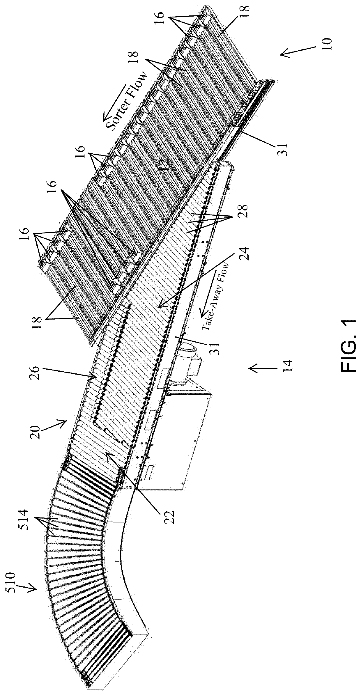
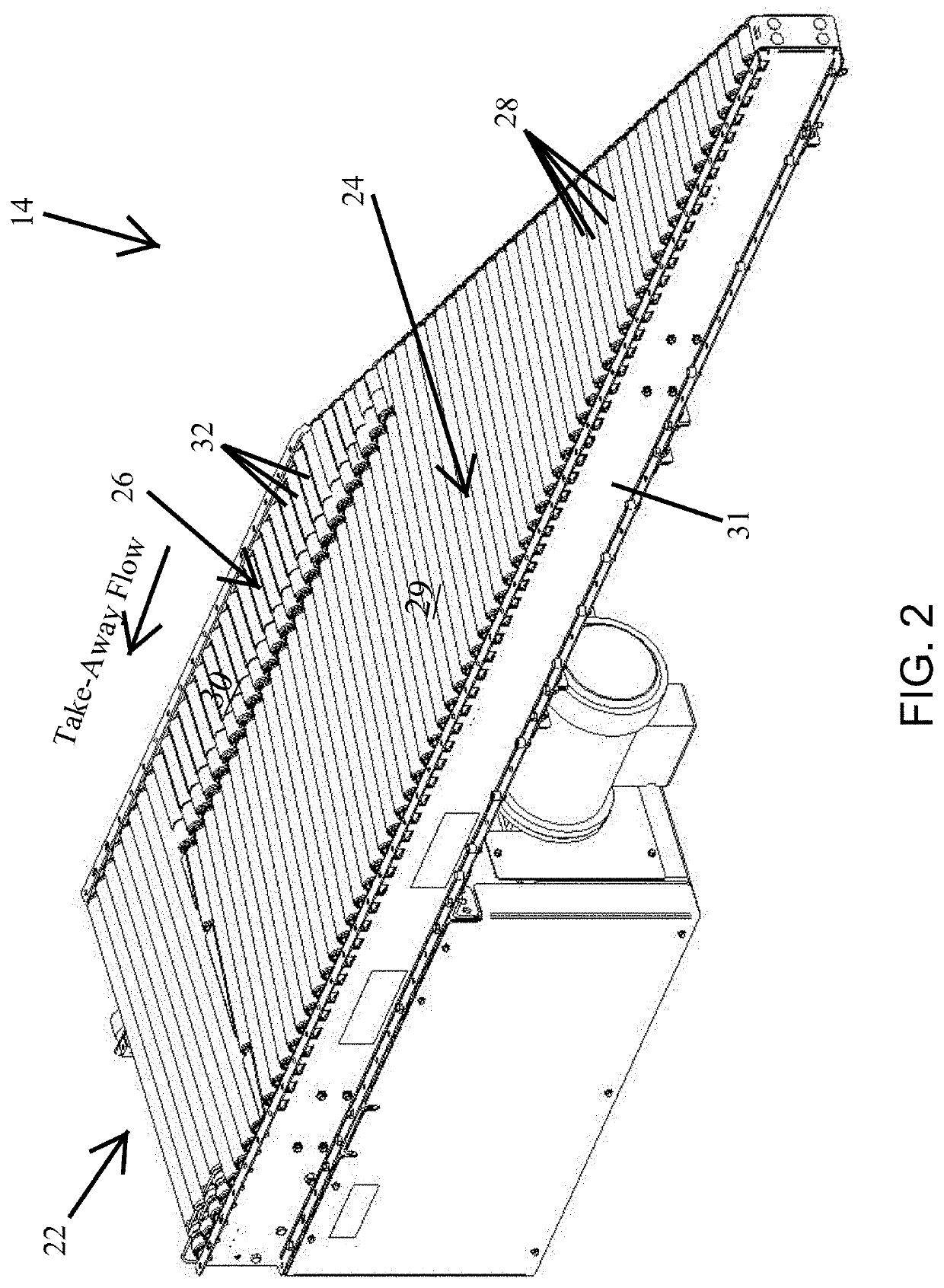
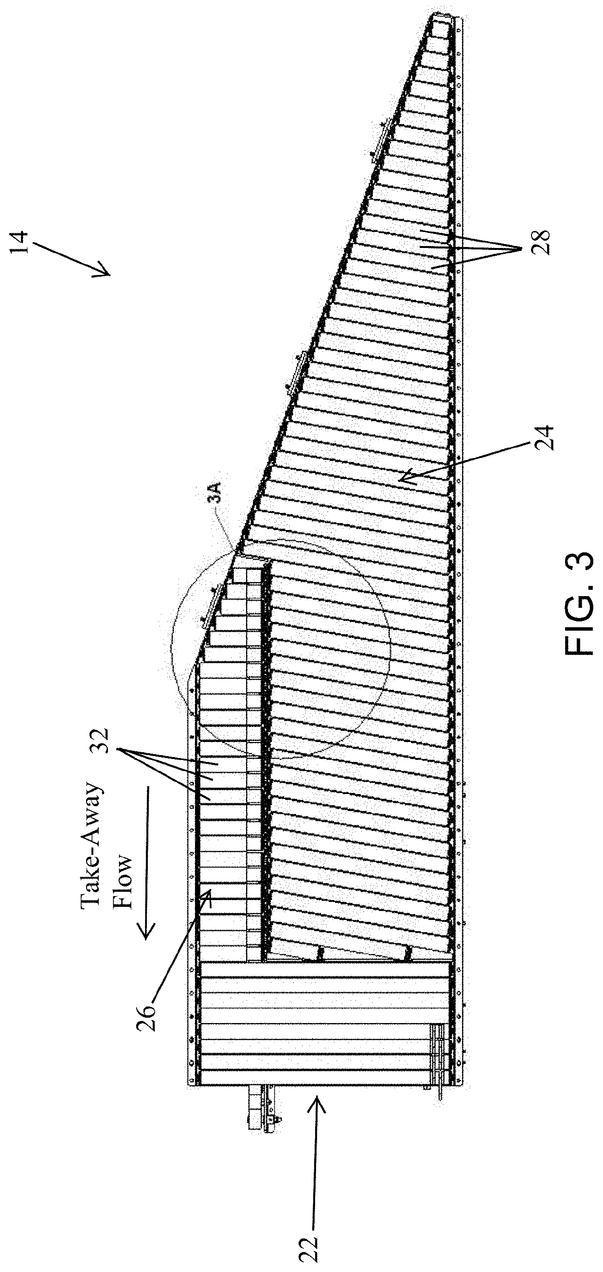
[0039]Referring now to the drawings and the illustrative embodiments depicted therein, a positive displacement sorter 10 includes a conveying surface 12 configured of interconnected slats 18 to convey articles in a longitudinal direction as illustrated by the sorter flow arrow and at least one diagonal take-away lane 14, extending diagonally from said conveying surface to receive articles being diverted from said conveying surface. (FIG. 1) Positive displacement sorter 10 is capable of diverting articles without rotating the articles and is thus a parallel diverter of the type disclosed in commonly assigned U.S. Pat. No. 6,814,216, the disclosure of which is hereby incorporated herein by reference. This is accomplished by a plurality of pushers 16 being configured to generally move together in a lateral direction in order to displace an item on conveying surface 12 to diagonal take-away lane 14.

[0040]A rotational system is configured to rotate a leading portion of a diverted article...


PUM


Abstract

A positive displacement sorter and method of diverting articles includes a conveying surface configured to convey articles in a longitudinal direction and at least one diagonal take-away lane, extending diagonally from the conveying surface to receive articles being diverted from said conveying surface. A plurality of pushers are configured to move together in a lateral direction in order to displace an item on the conveying surface to the diagonal take-away lane. A rotational system is configured to rotate a leading portion of a diverted article in the direction of the take-away lane. A belt drive system is provided for driving live roller conveyors about a curved section of a roller conveyor of the sorter. The drive belt is guided along a single conical drive plane that maintains the orientation of the drive belt relative to the single conical drive plane and limits twisting and stress in the drive belt.

Description

CROSS REFERENCE TO RELATED APPLICATION[0001]The present application claims priority of U.S. provisional applications Ser. No. 62 / 749,825 filed Oct. 24, 2018 and Ser. No. 62 / 749,707 filed Oct. 24, 2018, which are hereby incorporated herein by reference in their entireties.BACKGROUND OF THE INVENTION[0002]The present invention is directed to an article sorter apparatus and method of diverting articles and, in particular, to a positive displacement sorter and method that is capable of diverting at least some articles with more than one pusher shoe travelling together across a conveying surface to divert an article. Such diverting is known as parallel diverting. It should be understood that some parallel diverting sorters can also be capable of diverting articles with the pusher shoes extending diagonally across the conveying surface especially for long articles.[0003]One difficulty with parallel sorters is that the orientation of the diverted articles in a longitudinal direction does n...

Claims


Application Information

Patent Timeline
Patent Type & Authority Applications(United States)
IPC IPC(8): B65G13/10B65G13/07B65G13/071B65G47/84B65G47/30
CPCB65G13/07B65G47/844B65G13/10B65G13/071B65G2207/36B65G47/54B65G13/08
Inventor PILARZ, NOLAN R.COLE, VERONIQUEHEBBUR, SHREEDHAR MURTHYDUNCAN, JEFFERY D.THOMAS, NICHOLAS M.DEMAN, STEVEN M.KARAS, JOHN M.DEVRIES, JEFFREY S.BOORSMA, JEFFERY T.TRIESENBERG, THOMAS H.
Owner DEMATIC
Learn More