
Driving device for a processing machine

A driving mechanism, processing machine technology, applied in printing presses, rotary printing presses, general parts of printing machinery, etc.

Inactive Publication Date: 2010-06-23
MANROLANAD AG
View PDF3 Cites 0 Cited by
  • Summary
  • Abstract
  • Description
  • Claims
  • Application Information

AI Technical Summary

Problems solved by technology

[0004] The disadvantage of this drive mechanism structure is that the cylinders inside each printing unit and the cylinders / rollers arranged between them for conveying the substrate are connected to each other through a common gear transmission mechanism
As a result, automatic processes such as cleaning of cylinders or rollers, exchange of printing plates, or circumferential plate correction (Umfangsregisterkorrektur), which are carried out during operation of the printing press or when it is stopped, cannot be carried out or can only be carried out sequentially for a long time.

Method used


Image

  • Driving device for a processing machine
  • Driving device for a processing machine
  • Driving device for a processing machine

Examples


Embodiment Construction

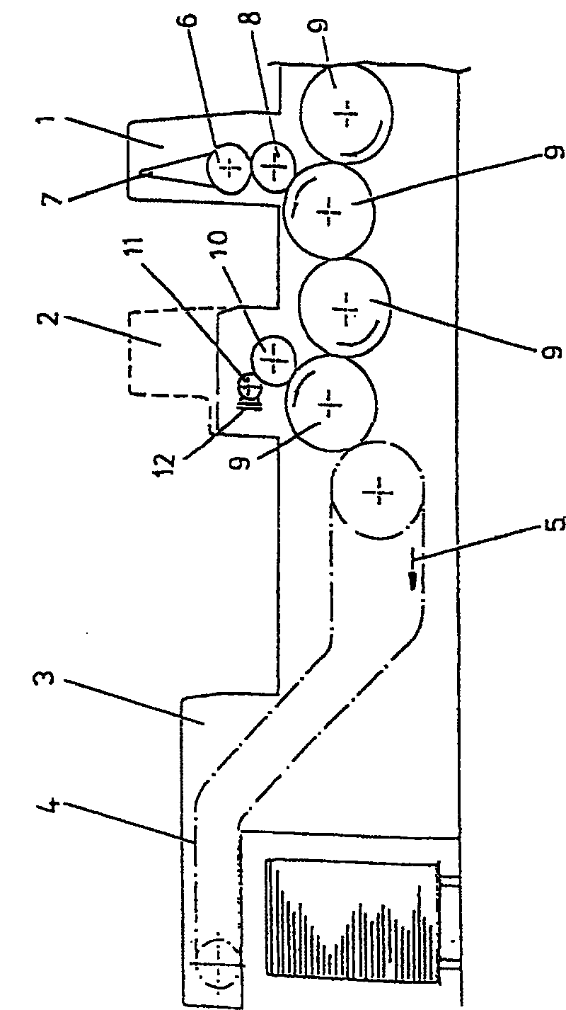
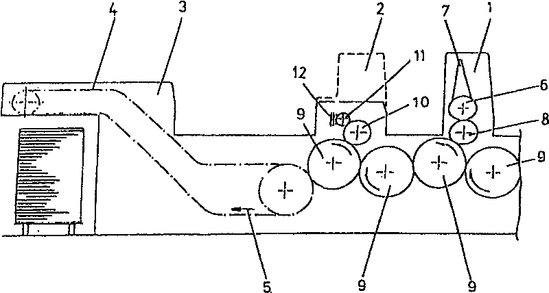
[0025] exist figure 1 The sheet-fed web printing press shown in includes at least one printing unit 1 , which is formed as an offset printing unit in a known manner from a plate cylinder 6 with associated inking unit 7 and a blanket cylinder 8 . A dampening unit is optionally assigned to the plate cylinder 6 upstream of the inking unit 7 in its direction of rotation. The sheet-fed web printing press also has at least one varnishing unit or flexographic printing unit 2 , which consists of a plate cylinder 10 and a metering system 11 , 12 . In this embodiment, the dosing system 11, 12 comprises, as is well known, a grid-configured inking roller 11 and a chamber doctor blade system 12 for processing paint, alternatively flexographic ink.

[0026] For conveying the printing material in the form of a printed sheet in the conveying direction 5 , a plurality of conveying cylinders 9 are provided, here a printed sheet guide cylinder with a gripper system. The varnishing unit / flexogr...


PUM


Abstract

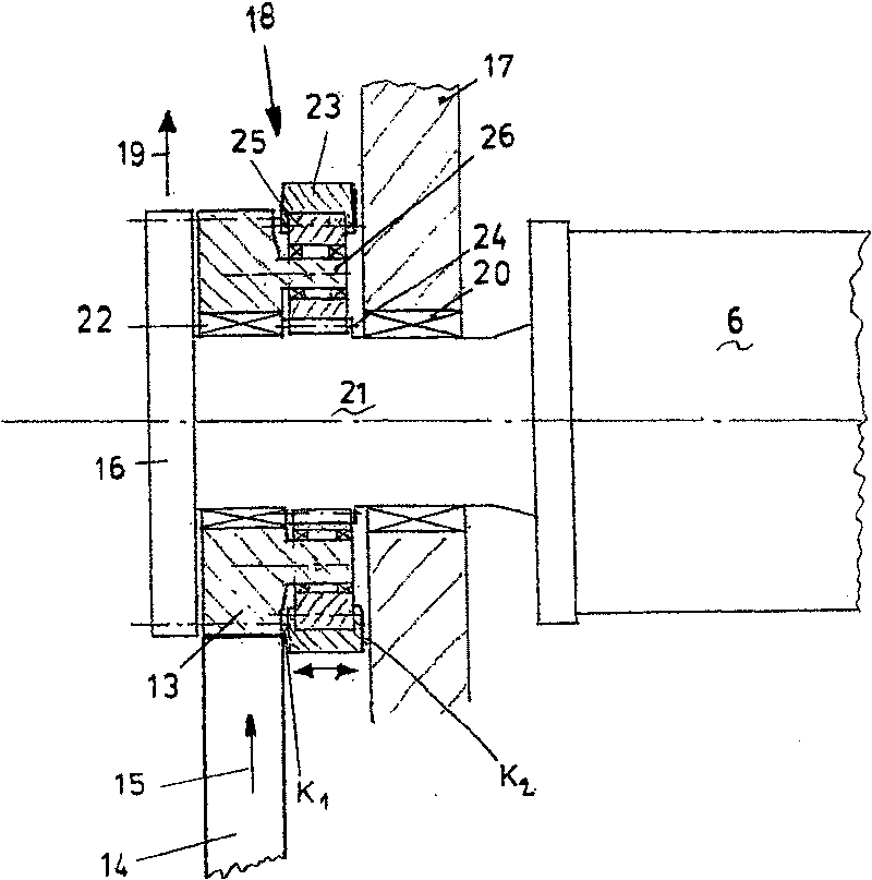
The printing press drive has a freely rotatable drive wheel on the platen / form cylinder (6, 10) and a mechanically coupled transfer transmission adjacent to this drive wheel. There is an input drive for on the said drive wheel actuated by the transfer transmission. In the first transfer stage, the transfer is synchronous at 1:1, and in at least one second stage, it is asynchronous at a different ratio with slow or fast drive to the inking mechanism (7).

Description

technical field [0001] The invention relates to a drive for a processing machine, in particular a printing press, which has at least one printing unit with a printing plate cylinder or printing plate cylinder. Background technique [0002] A drive mechanism of this type is known from DE 4241807A1. In such a drive mechanism for a printing press, the printing unit is coupled to the drive mechanism through a sliding gear (gear transmission mechanism). Motorized gear drives are provided for all cylinders for conveying the printing material, in particular blanket cylinders, and for all cylinders guiding the printing material (for example impression cylinders, deflection rollers, storage rollers, transfer rollers). Each plate cylinder is also coupled to the drive by means of a first gear transmission. [0003] A further separate drive is also provided for components not used for conveying the corresponding printing material, in particular the inking unit. The drive mechanism ha...

Claims


Application Information

Patent Timeline
Patent Type & Authority Patents(China)
IPC IPC(8): B41F13/008
CPCB41F31/004B41F13/0008B41F13/008
Inventor B·马纳思U·普舍尔
Owner MANROLANAD AG
Learn More