
Liquid crystal device and electronic device

a liquid crystal device and electronic device technology, applied in non-linear optics, instruments, optics, etc., can solve the problems of inability to achieve a small liquid crystal device, complicated structure, and increased cost, so as to facilitate the structural design of electronic devices and simplify the structure around the light emitting devices. , the effect of reducing the siz

Inactive Publication Date: 2005-05-24
BOE TECH GRP CO LTD
View PDF15 Cites 47 Cited by
  • Summary
  • Abstract
  • Description
  • Claims
  • Application Information

AI Technical Summary

Benefits of technology

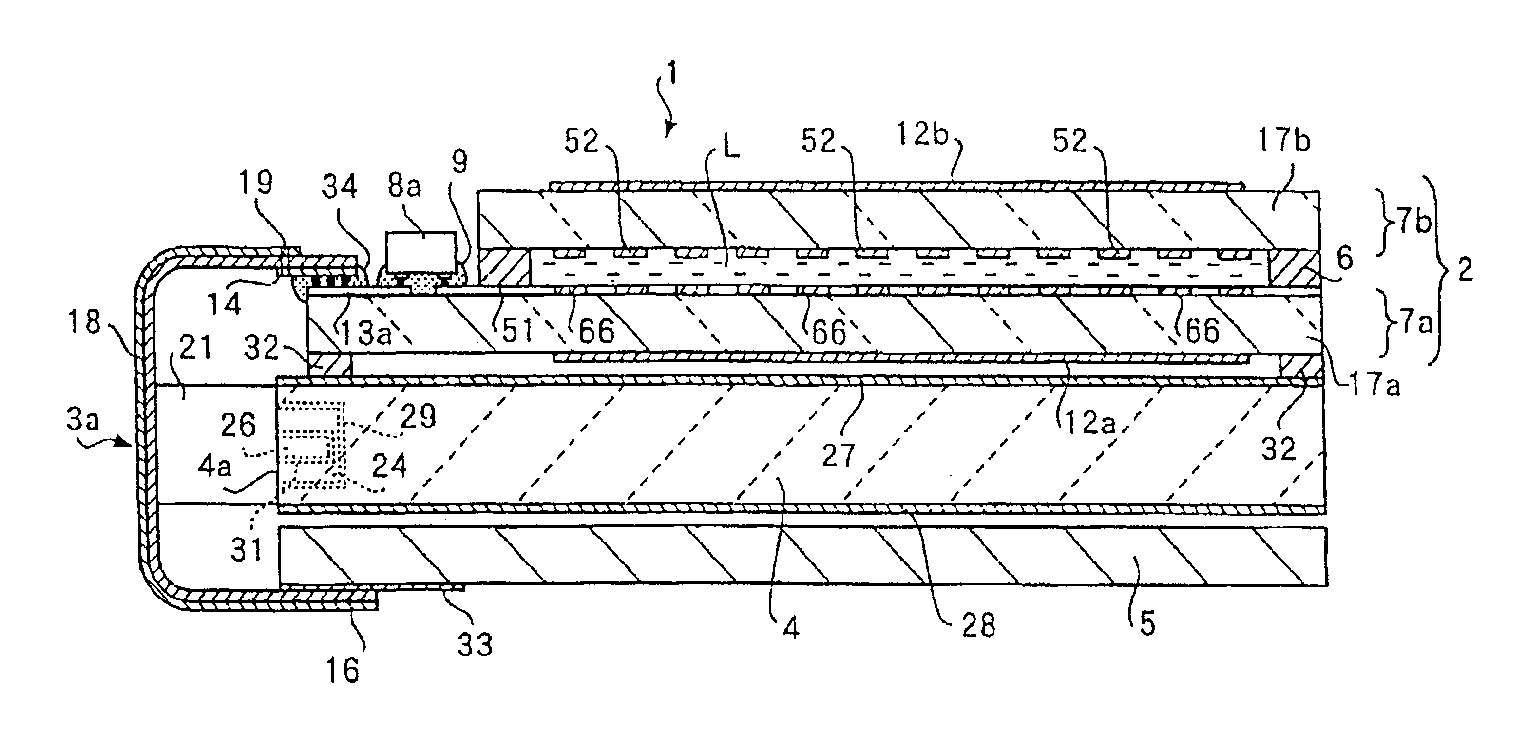
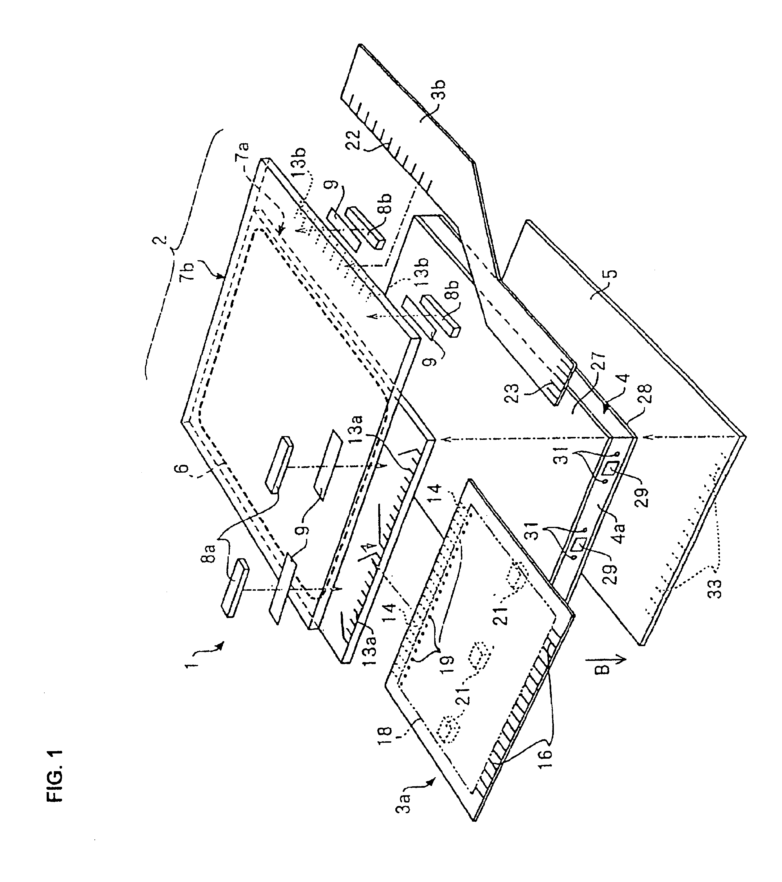
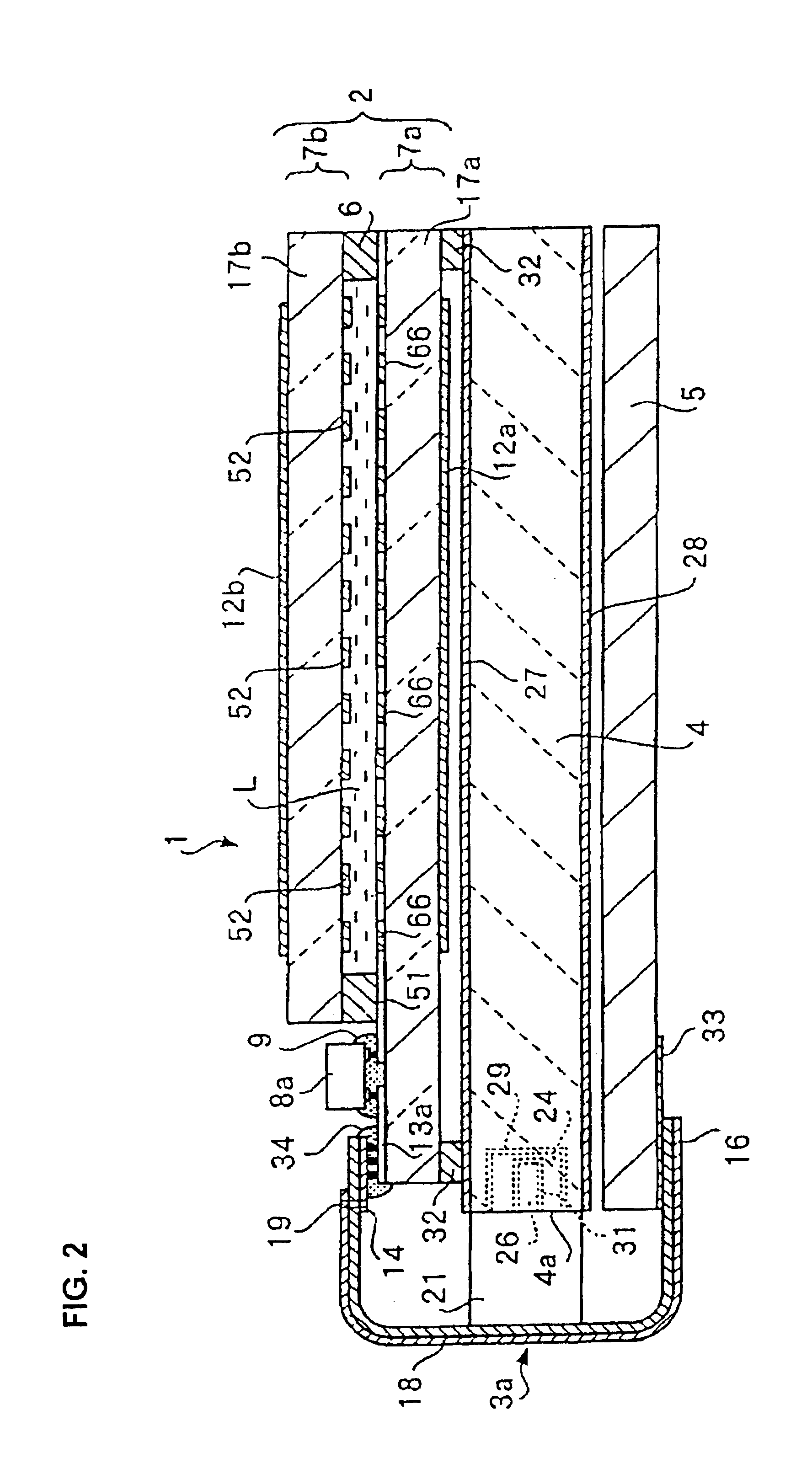
[0011]In this liquid crystal device, the light emitting device is provided on the flexible substrate (FPC: Flexible Printed Circuit) connected to one of the substrates which holds the liquid crystal therebetween. The flexible substrate is used for electrical wiring of some components to the liquid crystal, not for mounting the light emitting device to the light guide. Therefore, in the present invention, a supporting structure for the light emitting device can be greatly simplified to achieve reductions in the cost and size of the liquid crystal device.
[0033]In use of the liquid crystal device in accordance with the second aspect of the present invention, even when the structure around the light emitting device is simplified, as described above, the positioning means can prevent deviation of the position of the light emitting device relative to the light guide to prevent the occurrence of variation in the efficiency of light incidence on the light guide, thereby preventing the occurrence of variation in the light supplied to the liquid crystal. As a result, it is possible to securely prevent the occurrence of variation in brightness of an image displayed on a display area comprising the liquid crystal device from product to product in the electronic device, whereby many electronic devices with constant display quality can be stably manufactured.

Problems solved by technology

However, the conventional liquid crystal device having the above-described structure has the need to use a dedicated non-flexible substrate for the light emitting device and the need to form a structure for supporting the non-flexible substrate, thereby causing the problem of increasing the cost, complicating the structure and failing to achieve a small liquid crystal device.

Method used


Image

  • Liquid crystal device and electronic device
  • Liquid crystal device and electronic device
  • Liquid crystal device and electronic device

Examples


Embodiment Construction

[0047]According to the driving system, liquid crystal devices are possibly distinguished into an active matrix system liquid crystal device in which pixel electrodes are driven by switching elements (namely, nonlinear elements), and a passive matrix system liquid crystal device in which pixel electrodes are formed in a simple matrix arrangement without using switching elements. In comparison between both devices, the active matrix system is thought to be advantageous from the viewpoint of good contrast and responsiveness, and ease of achievement of a high-definition display.

[0048]Known systems of the active matrix system liquid crystal device include a system using a three-terminal element such as a thin film transistor (TFT) as a switching element, and a system using a two-terminal element such as a thin film diode (TFD). Of both systems, the liquid crystal device using TFDs has the advantages that no short-circuit defect occurs between wirings because there is no intersection betw...


PUM


Abstract

A liquid crystal 1 includes a pair of substrates 7a and 7b which hold a liquid crystal L therebetween, a light guide 4 provided opposite to one of the substrates, a FPC 3a connected to one of the substrates 7a and 7b, and a LED 21 provided opposite to a light receiving surface 4a of the light guide 4. The LED 21 is mounted on the FPC 3a and arranged opposite to the light receiving surface 4a of the light guide 4. The LED 21 is preferably positioned relative to the light guide 4 by engagement between the pines provided on the LED 21 and the recesses 31 provided on the light guide 4.

Description

BACKGROUND OF THE INVENTION[0001]1. Technical Field of the Invention[0002]The present invention relates to a liquid crystal device in which light transmitted through a liquid crystal is modulated by controlling the orientation of the liquid crystal to display an image. The present invention also relates to an electronic device using the liquid crystal device.[0003]2. Description of the Related Art[0004]Recently, liquid crystal devices have widely been used for electronic devices such as a computer, and a cell phone. The liquid crystal device generally comprises a liquid crystal sandwiched between a pair of substrates each comprising an electrode so that the orientation of the liquid crystal is controlled by applying a voltage between both electrodes to modulate light transmitted through the liquid crystal, to display an image.[0005]On the basis of the system for supplying light to the liquid crystal, various known liquid crystal devices are distinguished into a reflective liquid cry...

Claims


Application Information

Patent Timeline
IPC IPC(8): G02F1/1335G02F1/13G02F1/1365G02F1/13357G02F1/1345
CPCG02F1/133615G02F1/13452G02F1/1365G02F1/133
Inventor KAWAKAMI, HISANORIENDO, KOGO
Owner BOE TECH GRP CO LTD
Learn More