Blazed grating light valve

a light valve and grating technology, applied in the field of light modulators, can solve the problems of relatively difficult fabrication of light modulators and relatively expensive fabrication

Inactive Publication Date: 2005-05-24
SILICON LIGHT MACHINES CORP
View PDF3 Cites 1 Cited by
  • Summary
  • Abstract
  • Description
  • Claims
  • Application Information

AI Technical Summary

Benefits of technology

[0010]Each of the elongated elements comprises a blaze profile. Preferably, the blaze profile comprises a stepped profile across a width of each of the elongated elements where the blaze profile produces an effective blaze at a blaze angle. Alternatively, the blaze profile comprises a surface angled at the blaze angle.

Problems solved by technology

Further, the off-axis neck portions are critical to operation of the light modulator which necessitate tight tolerances for the off-axis neck portions making the light modulator relatively difficult to fabricate and also relatively expensive to fabricate.

Method used


Image

  • Blazed grating light valve
  • Blazed grating light valve
  • Blazed grating light valve

Examples


Embodiment Construction

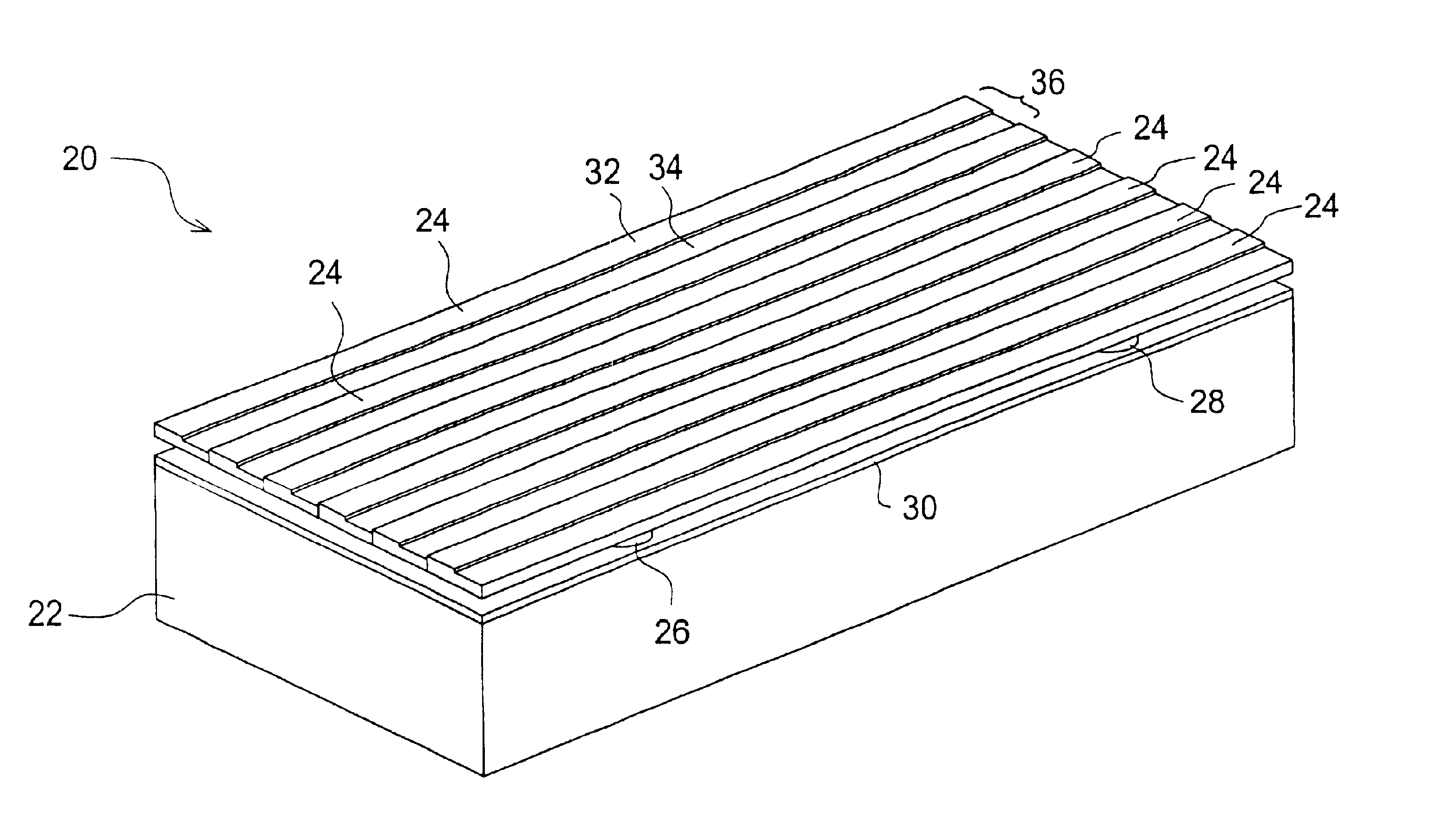
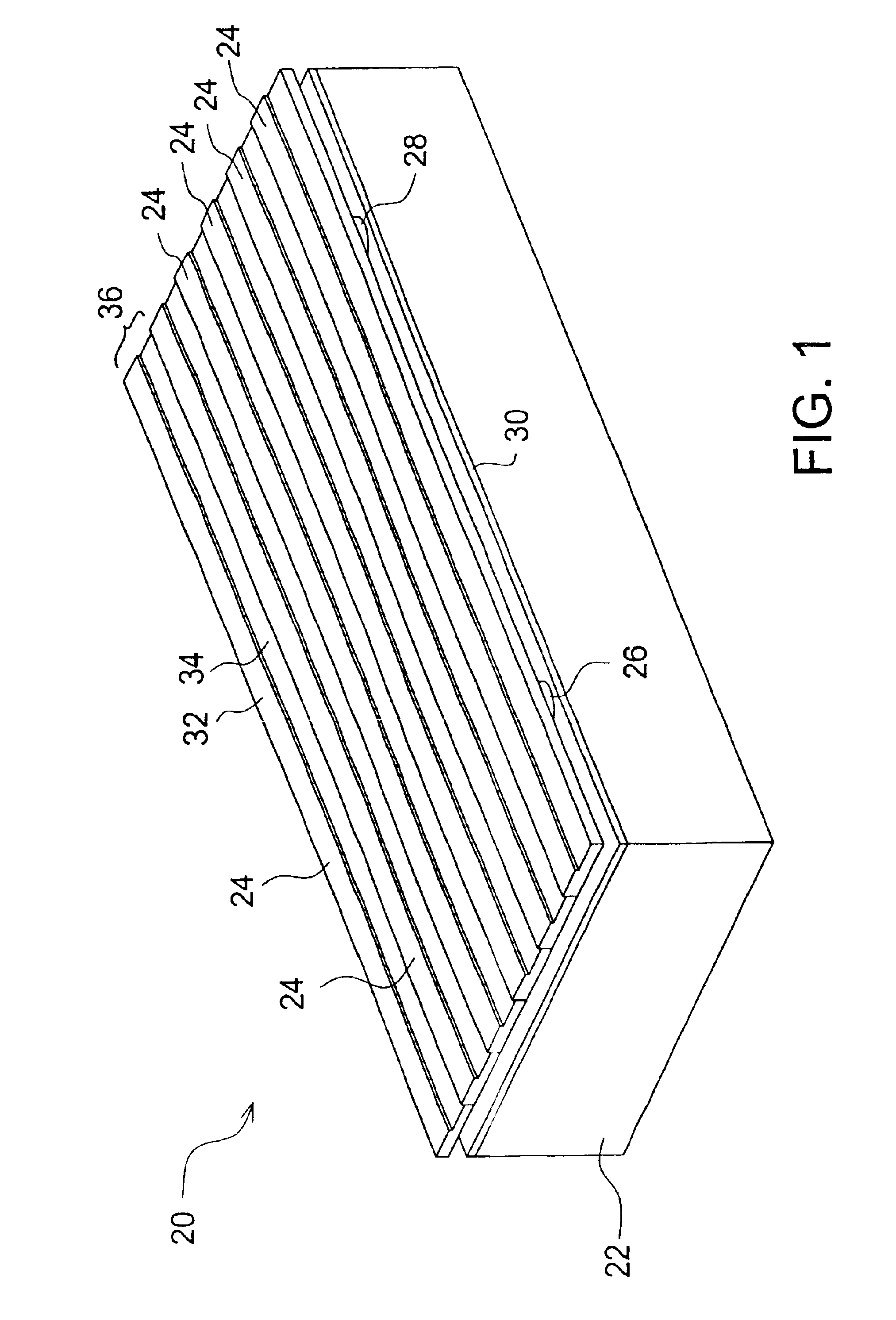
[0031]The preferred blazed grating light valve is illustrated isometrically in FIG. 1. The preferred blazed grating light valve 20 includes a substrate 22, elongated elements 24, first posts 26 (one shown), and second posts 28 (one shown). The substrate 22 includes a first conductor 30. The elongated elements 24 each preferably include a first surface 32 and a second surface 34, both of which are reflective. The first and second surfaces, 32 and 34, form a blaze profile 36 for each of the elongated elements 24. One of the first posts 26 and one of the second posts 28 couple each of the elongated elements 24 to the substrate 22. Each of the elongated elements 24 are also preferably coupled to the substrate 22 at first and second ends (not shown) of the elongated element 24.

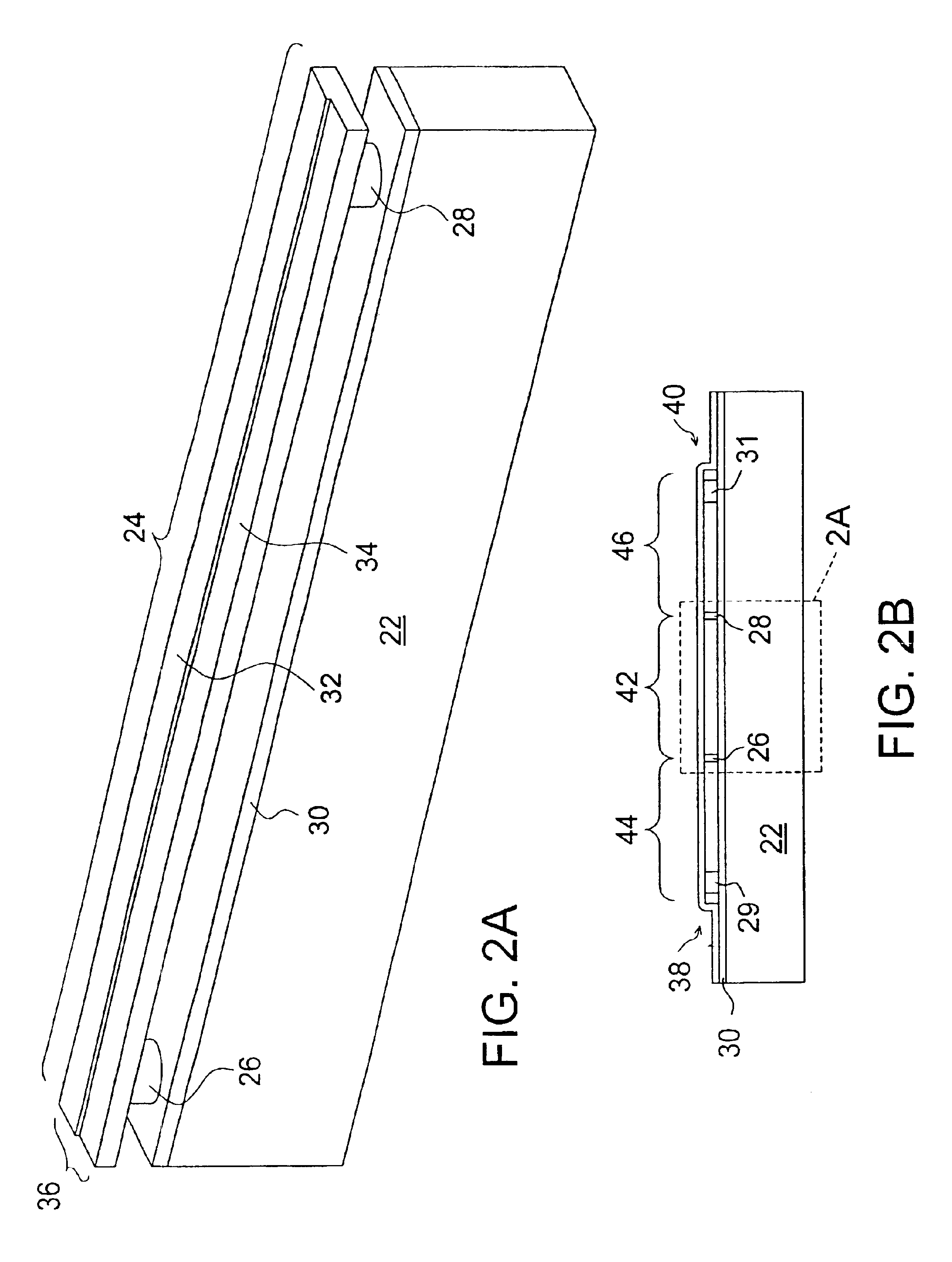
[0032]One of the elongated elements 24 and a portion of the substrate 22 are further illustrated isometrically in FIG. 2A. The elongated element 24 includes the first and second surfaces, 32 and 34, both of which a...


PUM

PropertyMeasurementUnit
widthaaaaaaaaaa
widthaaaaaaaaaa
second order diffraction angle θ2aaaaaaaaaa

Abstract

A light modulator includes elongated elements arranged parallel to each other. In a first diffraction mode, the light modulator operates to diffract an incident light into at least two diffraction orders. In a second diffraction mode, the light modulator operates to diffract the incident light into a single diffraction order. Each of the elongated elements comprises a blaze profile, which preferably comprises a reflective stepped profile across a width of each of the elongated elements and which produces an effective blaze at a blaze angle. Alternatively, the blaze profile comprises a reflective surface angled at the blaze angle. Each of selected ones of the elongated elements comprise a first conductive element. The elongated elements produce the first diffraction when a first electrical bias is applied between the first conductive elements and a substrate. A relative height of the blazed portions are adjusted to produce the second diffraction when a second electrical bias is applied between the first conductive elements and the substrate. In an alternative embodiment, each of the elongated elements includes the first conductive element and multiple elongated elements are arranged in groupings, where each of the groupings includes at least three of the elongated elements. When the multiple elongated elements are at a first height, the incident light reflects from the elongated elements. When relative heights of the multiple elongated elements are adjusted by applying individual electrical biases between the first conductive elements and the substrate, the incident light diffracts into the single diffraction order.

Description

RELATED APPLICATION(S)[0001]This is a divisional application of U.S. patent application Ser. No. 09 / 930,838, filed Aug. 15, 2001 now U.S. Pat. No. 6,829,092, entitled “BLAZED GRATING LIGHT VALVE”, the contents of which are hereby incorporated by reference.FIELD OF THE INVENTION[0002]This invention relates to the field of light modulators. More particularly, this invention relates to the field of light modulators where an incident light is modulated to produce a blazed diffraction.BACKGROUND OF THE INVENTION[0003]Bloom et al. in U.S. Pat. No. 5,311,360, entitled “Method and apparatus for modulating a light beam,” teach a grating light valve which operates in a reflection mode and a diffraction mode. The grating light valve includes elongated elements suspended above a substrate. In the reflective mode, reflective surfaces of the grating light valve cause incident light to constructively combine to form reflected light. In the diffractive mode, the reflective surfaces of the grating l...

Claims


Application Information

Patent Timeline
Patent Type & Authority Patents(United States)
IPC IPC(8): G02B26/08G02B5/18
CPCG02B26/0808G02B5/18
Inventor AMM, DAVID T.TRISNADI, JAHJAHUNTER, JAMESGUDEMAN, CHRISTOPHERMAHESHWARI, DINESH
Owner SILICON LIGHT MACHINES CORP
Why Eureka
Try Eureka