
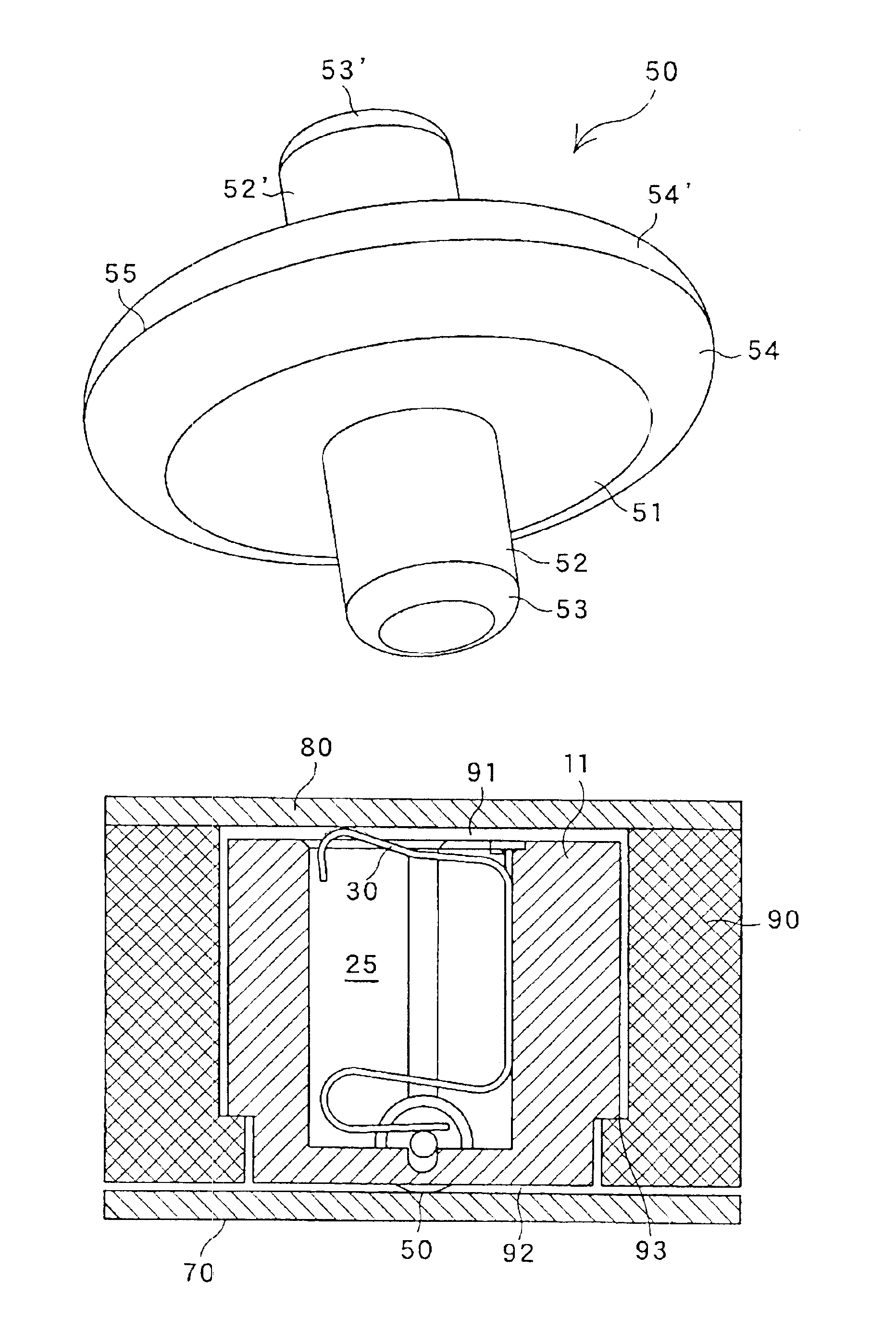
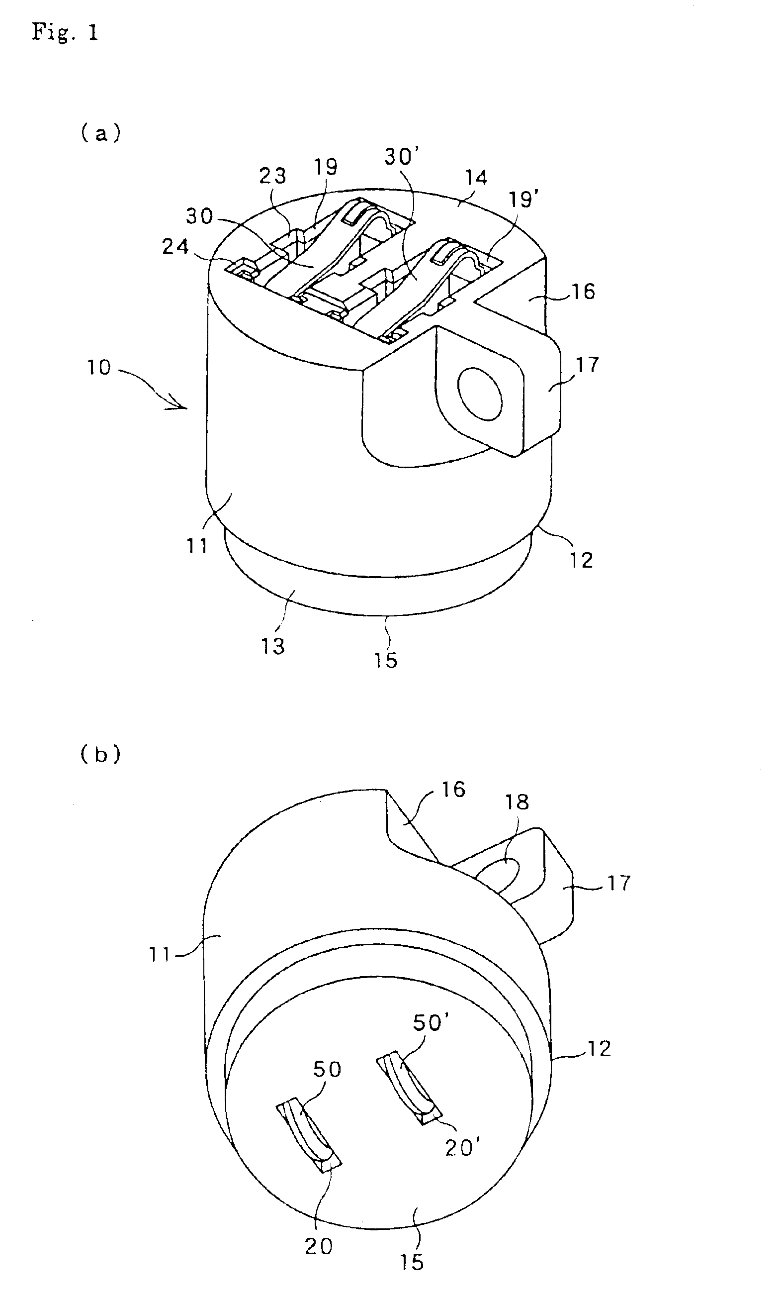
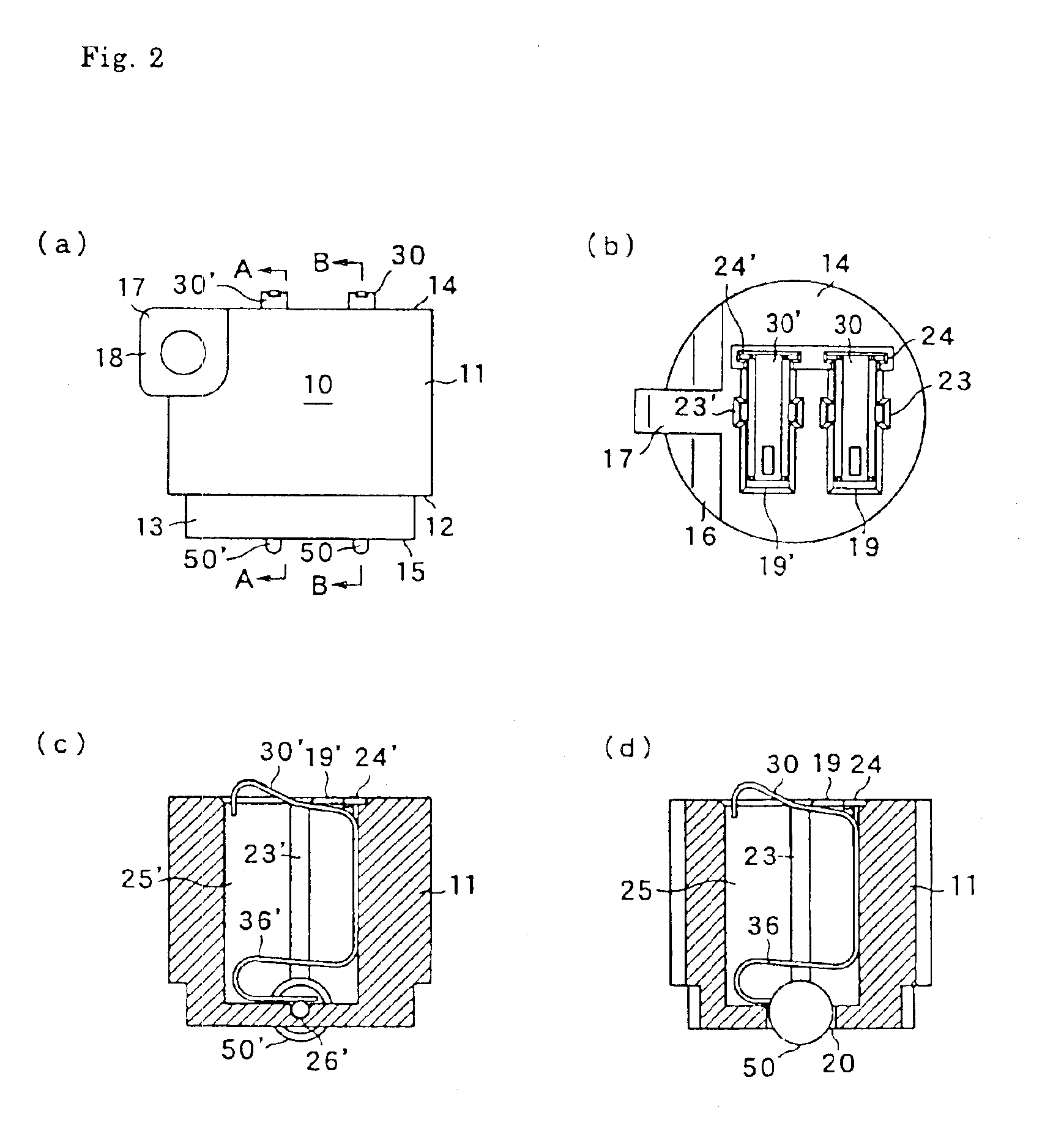
Hinge connector, and circuit board connected to connector

a technology of hinge connectors and circuit boards, applied in the direction of flexible/turnable line connectors, fixed connections, coupling devices, etc., can solve the problems of greatly reduced efficiency of assembling an applicance in an automatic assembly line, inconvenient use for users, and reduced wiring process, so as to simplify assembly work

Inactive Publication Date: 2005-05-24
JST MFG CO LTD
View PDF23 Cites 7 Cited by
  • Summary
  • Abstract
  • Description
  • Claims
  • Application Information

AI Technical Summary

Benefits of technology

[0009]The present invention aims to solve the abovementioned problems in the prior art, and therefore it is the object of the present invention to provide a hinge connector which is capable of simplifying the assembly work.
[0010]The present invention also aims to provide a hinge connector which ensures the smooth rotary movement of the contact portion as well as the maintenance of good contact, even when the contact pressure applied against the circuit board is increased.

Problems solved by technology

However, wiring by means of such a ribbon wire provides no physical support between interconnected members, thereby causing inconvenience to the user.
For instance, it is very difficult to insert a ribbon wire into a hole having a very small diameter in a cylindrical element at the time of wiring, and further, the wire is occasionally caught by members other than the cylindrical element, thereby causing in the wiring process.
Thus the efficiency of assembling an applicance in an automatic assembly line is greatly reduced.
As a result, the connector housing cannot be mounted on an element constituting the hinge mechanism, for example, a cylindrical element, making it impossible to miniaturize the connector.
H07-6842 has a very complicated structure, which is formed by mounting ring elements in the main shaft to the hinge mechanism, thereby making it impossible to mount the hinge mechanism upon the cylindrical element.
Furthermore, the connector disclosed in the Unexamined Japanese Patent Application under Publication No. 2000-268925 is of the press-contact type, and when such type is used in the above-mentioned hinge mechanism, the repetitive application of the rotary movement causes the reduction of contact reliability and deterioration of the rotary moving property due to the torsion applied to a contact in the rotary movement of the circuit board.

Method used


Image

  • Hinge connector, and circuit board connected to connector
  • Hinge connector, and circuit board connected to connector
  • Hinge connector, and circuit board connected to connector

Examples


first embodiment

[0054]The present invention is not limited to the above-mentioned embodiments, as various modifications are possible. In the hinge connector 10 of the first embodiment, the connection of the connector to the circuit board 80 is established by contact pressure. However, a solder connection or a plug-in connection to a connector of another type can also be employed in accordance with the design concept of the hinge mechanism. These embodiments are described herein below.

second embodiment

[0055]FIG. 8 shows a hinge connector in the FIGS. 8(a) and 8(b) are side views thereof.

[0056]The hinge connector 110 has substantially the same structure as the hinge connector 10 of the first embodiment, except that the external contact areas 34 and 34′ of the elastic contact elements 30 and 30′ in the hinge connector 10 are replaced with solder terminals.

[0057]In other words, the main body 111, step 112, end portion 113, head portion 114, bottom portion 115, flat portion 116, mounting hook 117 and mounting hole 118 of the hinge connector 110 are equivalent to the main body 11, step 12, end portion 13, head portion 14, bottom portion 15, flat portion 16, mounting hook 17 and mounting hole 18 of the hinge connector 10. Moreover, wheel type contacts 150 and 150′ correspond to the wheel type contacts 50 and 50′ of the hinge connector 10. In this case, the external contact portions of the elastic contact element are constituted in the form of flat terminals 134 and 134′ capable of pro...

third embodiment

[0059]FIG. 9 shows a hinge connector in the FIGS. 9(a) and 9(b) are side views thereof.

[0060]The hinge connector 210 has substantially the same structure as the hinge connector 10 of the first embodiment, except that the external contact areas 34 and 34′ of the elastic contact elements 30 and 30′ in the hinge connector 10 are replaced with projecting plug-in terminals.

[0061]In other words, the main body 211, step 212, end portion 213, head portion 214, bottom portion 215, flat portion 216, mounting hook 217 and mounting hole 218 of the hinge connector 210 are equivalent to the main body 11, step 12, end portion 13, head portion 14, bottom portion 15, flat portion 16, mounting hook 17 and mounting hole 18 of the hinge connector 10. Moreover, the wheel type contacts 250 and 250′ correspond to the wheel type contacts 50 and 50′ of the hinge connector 10. In this case, the external contact portions of the elastic contact element are constituted in the form of plug-in terminals 234 and ...


PUM


Abstract

A hinge connector comprising an insulative connector housing (10) having a predetermined shape, a through hole extending through the connector housing, a receiving chamber defined in the through hole, and an elastic contact member (30) having electric conductivity and a rotatable contact member (50) that are received in the receiving chamber, wherein the elastic contact member (30) is elastically contacted at one end thereof with the rotatable contact member (50), and projects at the other end out of the through hole to form an external contact. This hinge connector is mounted on the main body housing (90) of an electronic device, a circuit board (70) is connected to a cover body, and the contact member (50) is disposed to make rotation contact with the pattern on the circuit board. Such arrangement provides a hinge connector wherein the contact smoothly rotates even if the contact pressure on the circuit board is increased, and good contact can be maintained.

Description

TECHNICAL FIELD[0001]The present invention relates to a connector, which is used in various kinds of electronic appliances, such as cellular phones, personal computers and the like, and more specifically to a hinge connector, which is suitable for connecting the electric circuit of the main body of the appliance to the electric circuit of a lid member thereof, where the main body and the lid member are joined to each other by a hinge mechanism. The present invention also relates to a circuit board connected to such a connector.BACKGROUND ART[0002]In compact electronic appliances, cellular phones, personal computers and the like, a hinge mechanism is traditionally used to pivotally couple the main body of an appliance to a lid member, and the electronic circuit of the main body is electrically connected to the electric circuit of the lid member via a flexible ribbon wire inserted into a cylinder element in the hinge mechanism.[0003]However, wiring by means of such a ribbon wire provi...

Claims


Application Information

Patent Timeline
Patent Type & Authority Patents(United States)
IPC IPC(8): H01R35/00H01R12/00H01R13/24H01R12/16H01R13/22H01R35/04H01R39/00H01R39/64H01R13/20
CPCH01R12/57H01R13/2435H01R12/714H01R12/7082H01R35/04H01R39/643
Inventor HARASAWA, MASAAKI
Owner JST MFG CO LTD
Learn More