
Method and system for querying in a moving object database

a database and moving object technology, applied in the field of tracking moving objects, can solve the problems of unsatisfactory bandwidth spike on the network, limited system resources such as bandwidth and processing power, and trade-off between precision and resources

Inactive Publication Date: 2005-05-17
FLUENSEE +1
View PDF17 Cites 196 Cited by
  • Summary
  • Abstract
  • Description
  • Claims
  • Application Information

AI Technical Summary

Benefits of technology

[0019]The system also defines a set of operators that can be used to query trajectory data in the moving object database. For example, a query might find the objects that will be within 1 mile of a certain location at a given time. The operators may also be used to notify a user when specific condition occurs. For example, a user may be notified when an object is expected to be late by more than one hour. The operators can be incorporated into the traditional SQL query language, which has been widely adopted by many commercial database systems. The new operators allow for the development of complex spatial and temporal applications.

Problems solved by technology

First, point-location management does not allow interpolation or extrapolation of data. In point-location management, the system only knows the time-location points stored in its database. It cannot interpolate the past position of a moving object, for example at time X, using data sets subsequent to that time. Also, it cannot extrapolate a future location of the moving object from past data sets. In addition, the point-location management system has difficulty determining the current location of all its moving objects. Since the system does not support extrapolation, to find the current location of its moving objects the system must simultaneously poll each moving object. This causes an undesirable bandwidth spike on the network as the system attempts to contact each object. Objects disconnected from the network are not polled, and their location will not be known.
A second disadvantage is that point-location leads to a tradeoff between precision and resources.
This consumes limited system resources such as bandwidth and processing power.
When these resources are not taxed by frequent location updates, the location information quickly becomes dated and, therefore, imprecise.
A third problem of point-location management is that it leads to cumbersome and inefficient software development.
This creates several problems for developing location based service applications.
Existing DBMS's are not well equipped to handle continuously changing data, such as the location of moving objects, because in existing databases data is assumed to be constant unless it is explicitly modified.
Location based service applications also need to manage space and time information; however, SQL is not designed or optimized for these types of when / where queries.
For example, the query “retrieve the vehicles that are inside the region R always between 4 pm and 5 pm” would be extremely difficult to express in SQL.
Additionally, moving object locations are inherently imprecise because the database location of the object (i.e., the object location stored in the database) cannot always be identical to the actual location of the object.
This inherent uncertainty impacts database modeling, querying and indexing.
Furthermore, existing DBMS's have no parameters to account for varying levels of uncertainty, such as was that truck within 100 inches, 100 feet, 100 yards, or 100 miles of an intermediate point calculated.

Method used


Image

  • Method and system for querying in a moving object database
  • Method and system for querying in a moving object database
  • Method and system for querying in a moving object database

Examples


example database

SYSTEM CONFIGURATION

[0200]A mobile object database (MOD) can be implemented in many different configurations. In a preferred embodiment, the MOD provides inheritable abstract data types (ADTS) for moving objects, a set of query operators, methods to define and manipulate the abstract data types, and geodetic and trajectory finding services. When combined with the application tier, the MOD can connect to wireless and World Wide Web (WWW) applications.

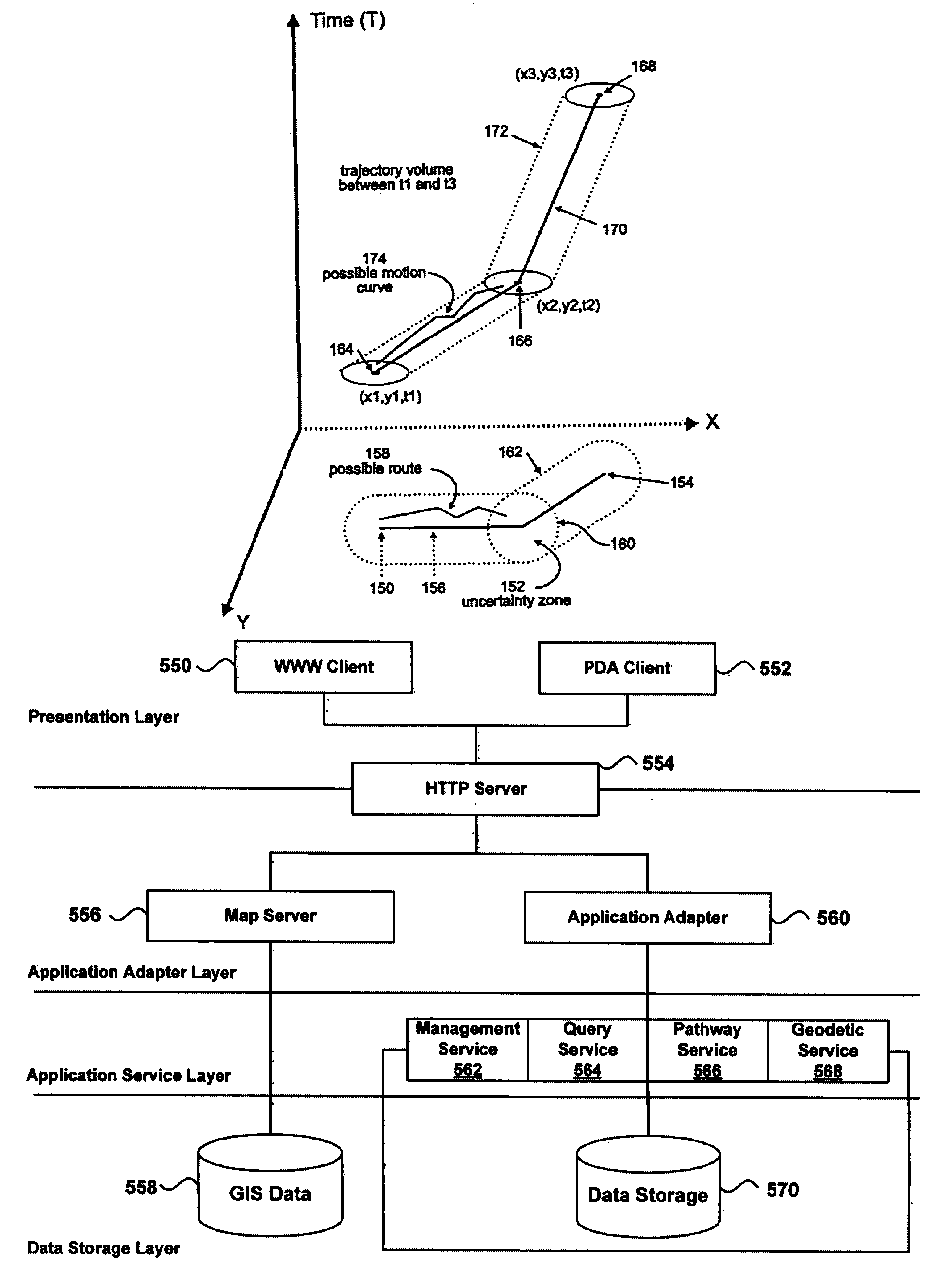
[0201]FIG. 12 depicts an exemplary configuration for the database. The database uses two types of clients, a WWW client 550 and a PDA client 552; however, it is possible to use additional or fewer clients. The WWW client 550 monitors moving objects. Users may use the WWW client 550 to query the moving objects, monitor and review their motion, and communicate with the database or with other devices. It can display a graphical user interface of various queries, and it may provide trajectory visualization, triggers and notifications. Additi...


PUM


Abstract

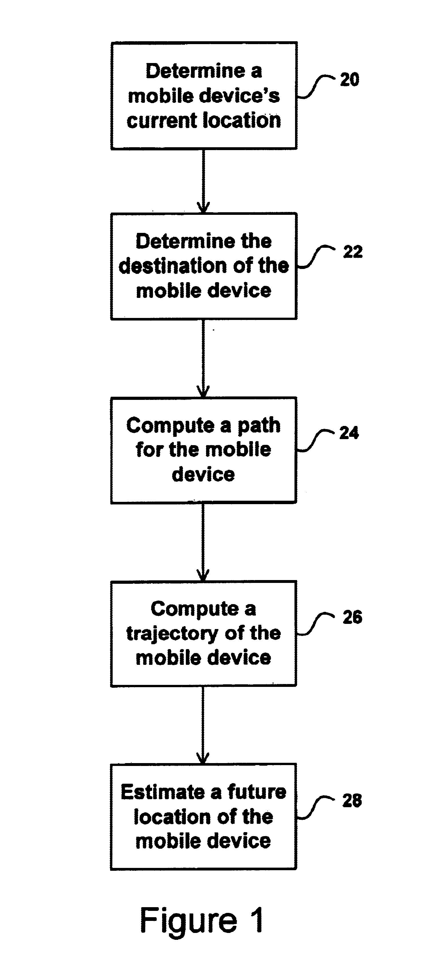
A database receives location information about a moving object. Using the destination of the object and an electronic map, the database finds a projected path for the moving object. From the projected path, the database computes a trajectory. The trajectory may be used to estimate past and future positions of the moving object. The moving object may send location updates to the database when its actual location differs from its anticipated location by more than an uncertainty threshold.

Description

RELATED APPLICATIONS[0001]This application claims priority from U.S. Provisional Patent Application No. 60 / 243,839 filed Oct. 30, 2000, and from U.S. Provisional Patent Application No. 60 / 292,322 filed May 22, 2001. U.S. Provisional Patent Application No. 60 / 243,839 filed Oct. 30, 2000, is incorporated herein by reference in its entirety. U.S. Provisional Patent Application No. 60 / 292,322 filed May 22, 2001, is incorporated herein by reference in its entirety.GOVERNMENT RIGHTS[0002]This invention was made with government support under grant numbers ITR-0086144, CCR-9816633, CCR-9803974, IRI-9712967 and INT-9812325 sponsored by the National Science Foundation, and DAAL01-96-2-0003, mods 18 and 34, sponsored by the Army Research Laboratories. The government may have certain rights in this invention.BACKGROUND[0003]1. Field of the Invention[0004]This invention relates to tracking moving objects. More specifically, it relates to using past location and future destination information to ...

Claims


Application Information

Patent Timeline
Patent Type & Authority Patents(United States)
IPC IPC(8): G01C23/00G01C21/26G06F19/00G01C21/30G01C21/34G08G1/123
CPCG01C21/3415G08G1/20Y10S707/99933
Inventor WOLFSON, OURI
Owner FLUENSEE
Learn More