Eureka AIR delivers breakthrough ideas for toughest innovation challenges, trusted by R&D personnel around the world.

Extended bandwidth mirror

a mirror and bandwidth technology, applied in the field of thin film mirrors, can solve the problems of not having enough broadband reflectance zones to allow connection with the wavelength range of laser wavelengths used in certain optical systems, and not being able to provide a single dielectric mirror. sensitivity of such a system is severely limited

Inactive Publication Date: 2005-05-17
IDEX HEALTH & SCI
View PDF6 Cites 45 Cited by
  • Summary
  • Abstract
  • Description
  • Claims
  • Application Information

AI Technical Summary

Benefits of technology

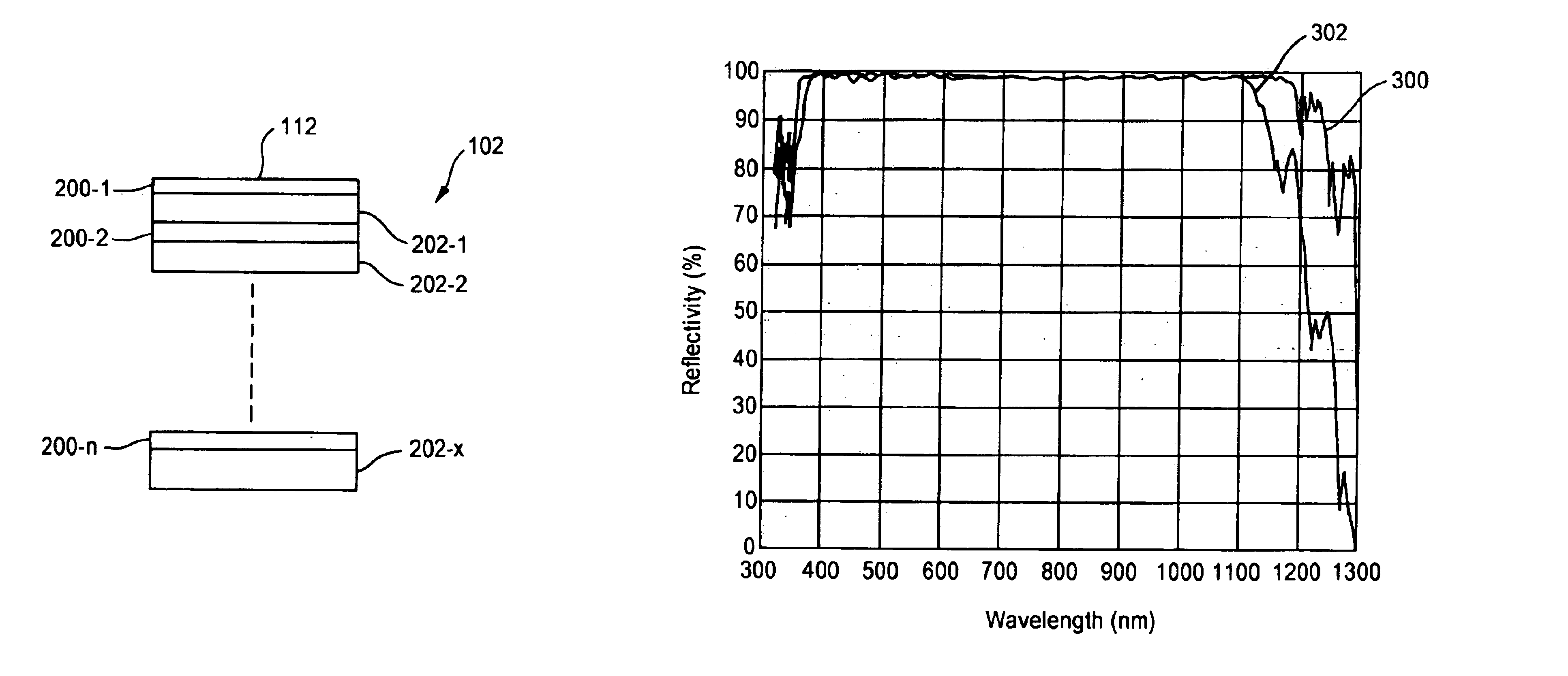
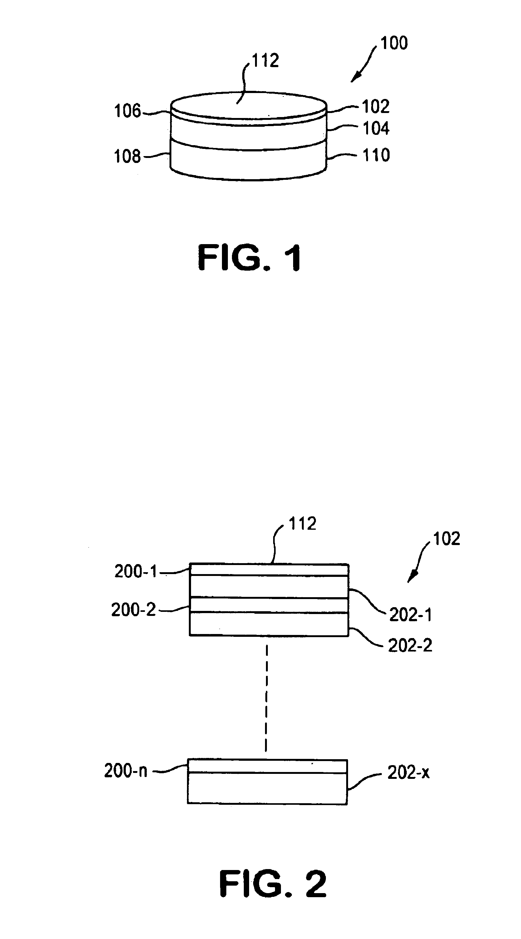
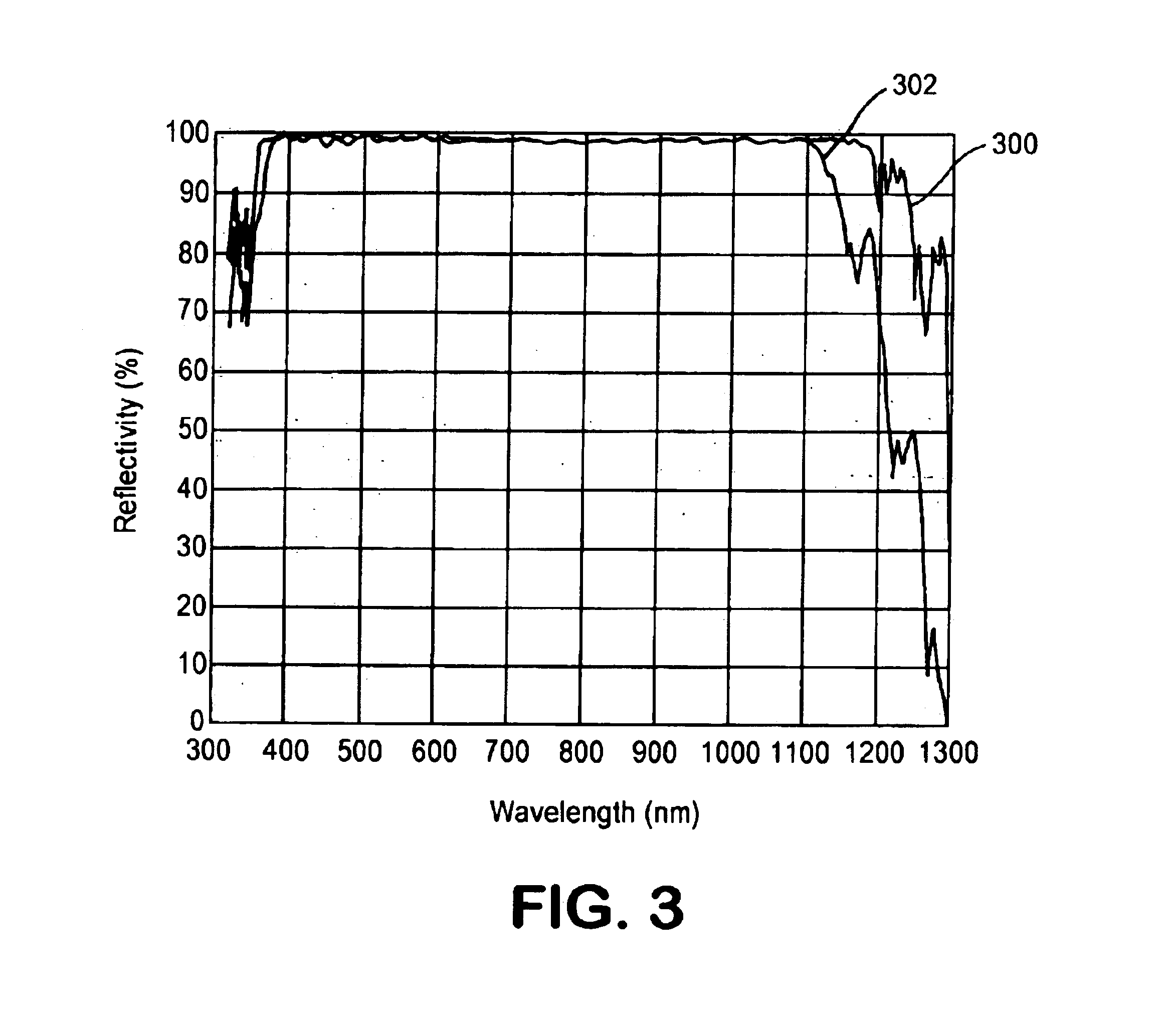
[0009]According to one aspect of the invention, there is provided a mirror including a substrate and a reflector portion disposed directly on a surface of the substrate. The reflector portion includes alternating layers of high and low index of refraction material configured for reflecting greater than 99% of all wavelengths in a bandwidth of greater than 400 nm at greater than 97.5% reflectivity. The bandwidth includes at least one wavelength in the range from 350 nm to 1100 nm. In one embodiment, the layers are configured for reflecting greater than 99% of all wavelengths in the range from 400 nm to 1100 nm at greater than 98% reflectivity at a plurality of angles of incidence for each wavelength.
[0010]According to another aspect of the invention, the reflector portion of a mirror consistent with the invention includes in excess of 150 alternating layers of high and low index of refraction dielectric material. A first one of the high index of refraction materials alternates with the low index of refraction material adjacent the substrate, and a second one of the high index of refraction materials alternates with the low index of refraction material adjacent a top surface of the reflector portion. The layers are configured for reflecting an s-polarization and p-polarization of greater than 99% of all wavelengths in a bandwidth of greater than 400 nm at greater than 97.5% reflectivity.

Problems solved by technology

A major disadvantage associated with conventional dielectric mirrors, however, is that they do not have sufficiently broadband reflectance zones to allow use in connection with the range of laser wavelengths used in certain optical systems.
Conventionally, it has not been possible to provide a single dielectric mirror that provides high reflectivity of all polarization states in this range of fundamental and harmonic frequencies, plus all wavelengths in between.
Because of the low light levels involved, the sensitivity of such a system is severely limited by the difficulty of attaining a single mirror that directs both the excitation and the fluorescence light.
Despite use of chirped stacks, deposition processes used for depositing the thin-film layers have provided practical limitations to producing mirrors with high reflectance over a broad range of wavelengths.
In addition, random thickness errors that occur during deposition can also reduce reflectance over a portion of the spectral region.
However, mirrors having high reflectance / low transmittance over a wide range of wavelengths make optical monitoring in conventional deposition systems difficult.

Method used


Image

  • Extended bandwidth mirror
  • Extended bandwidth mirror
  • Extended bandwidth mirror

Examples


Embodiment Construction

[0023]The present invention will be described herein in connection with various exemplary embodiments thereof. Those skilled in the art will recognize that the features and advantages of the present invention may be implemented in a variety of configurations. It is to be understood, therefore, that the embodiments described herein are presented by way of illustration, not of limitation.

[0024]Conventional reflecting mirrors have been configured as dielectric mirrors having high reflectivity over a relatively narrow (e.g. less than or equal to 400 nm) band of wavelengths associated only with, for example, one operating frequency of the laser 100, or associated with only one laser system. An Nd: YAG laser, for example, has fundamental and harmonic frequencies of 1064 nm, 532 nm and 355 nm. No known conventional dielectric mirror provides high reflectivity for all polarization states over the range of 355 nm to 1064 nm, which covers the fundamental and harmonic frequencies of an Nd:YAG ...


PUM


Abstract

A dielectric mirror including a substrate and a reflector portion disposed directly on the substrate. The reflector portion includes alternating layers, e.g. in excess of 150 alternating layers, of high and low index of refraction material. In one embodiment, the layers are configured for reflecting each wavelength in a bandwidth of 400 nm at greater than 97.5% reflectivity. In another embodiment, the layers are configured for reflecting an s-polarization and p-polarization of each wavelength in the range from 350 nm to 100 nm at greater than 98% reflectivity. High reflectivity is achieved for a wide range of angle of incidence.

Description

CROSS REFERENCE TO RELATED APPLICATIONS[0001]The present application claims the benefit of the filing date of U.S. Provisional Application No. 60 / 409,170, filed Sep. 9, 2002 the teachings of which are incorporated herein by reference.FIELD OF THE INVENTION[0002]The present invention relates in general to reflective devices, and in particular to thin film mirrors useful, for example, in laser systems.BACKGROUND OF THE INVENTION[0003]Conventionally, laser mirrors have been constructed from multiple layers of two or more dielectric materials having different refractive indices. Each layer is very thin, i.e. having an optical thickness (physical thickness times the refractive index of the layer) on the order of order of ¼ wavelength the light to be reflected in the application. The layers may be deposited on a substrate to provide a high reflectance region extending over a limited range of wavelengths.[0004]It has been recognized that dielectric mirrors provide both a higher reflectance...

Claims


Application Information

Patent Timeline
Patent Type & Authority Patents(United States)
IPC IPC(8): G02B5/08G02B5/30
CPCG02B5/3041G02B5/0833
Inventor MIZRAHI, VICTORWANG, LIGANG
Owner IDEX HEALTH & SCI
Why Eureka
Eureka Blog
Learn More