Reciprocating motor

a technology of reciprocating motors and motors, which is applied in the direction of dynamo-electric machines, dynamo-electric components, magnetic circuit shapes/forms/construction, etc., can solve the problems of reducing the efficiency of the motor, and limiting the form to be thin and easy to break, so as to prevent the efficiency degradation of the motor and minimize the loss of flux

Inactive Publication Date: 2005-05-17
LG ELECTRONICS INC
View PDF13 Cites 8 Cited by
  • Summary
  • Abstract
  • Description
  • Claims
  • Application Information

AI Technical Summary

Benefits of technology

[0019]Therefore, an object of the present invention is to provide a reciprocating motor that is capable of preventing efficiency degradation of a motor by forming a portion of a magnet frame at which a magnet is fixed with a non-metallic material to thereby minimize a loss of a flux generated from a winding coil.
[0020]Another object of the present invention is to provide a reciprocating motor in which a portion of a magnet frame to which an element to be reciprocally moved is engaged is made of a metallic material having a certain strength, thereby making it thin and maintaining a combination strength with the element.
[0021]Still another object of the present invention is to provide a reciprocating motor in which, in molding a magnet frame, no pull-out draft is required, so that the magnet frame can be formed with an even thickness, and an air gap between an outer stator core and an inner stator core is narrowed to thereby improve an efficiency of a motor.

Problems solved by technology

However, in the case that the magnet frame 114 is made of a non-magnetic metal, since a conductivity still exists in terms of the characteristics of the metal, a magnetic field generated between the outer stator core 106 and the inner stator core 108 is leaked along the magnet frame 114, causing a problem of degradation of the performance of the motor.
If the magnet frame is made of a non-metallic material in view of solving such a problem, since the non-metallic material has a weak physical property compared to a metallic material in view of its characteristics, there is a limitation to form it to be thin and can be easily broken in the linear and reciprocal movement.
Then, however, the air gap between the outer stator core 106 and the inner stator core 108 is enlarged to degrade the efficiency of the motor.

Method used


Image

  • Reciprocating motor
  • Reciprocating motor
  • Reciprocating motor

Examples


Embodiment Construction

[0040]Reference will now be made in detail to the preferred embodiments of the present invention, examples of which are illustrated in the accompanying drawings.

[0041]There may exist a plurality of embodiments of a reciprocating motor in accordance with the present invention, of which the most preferred one will now be described.

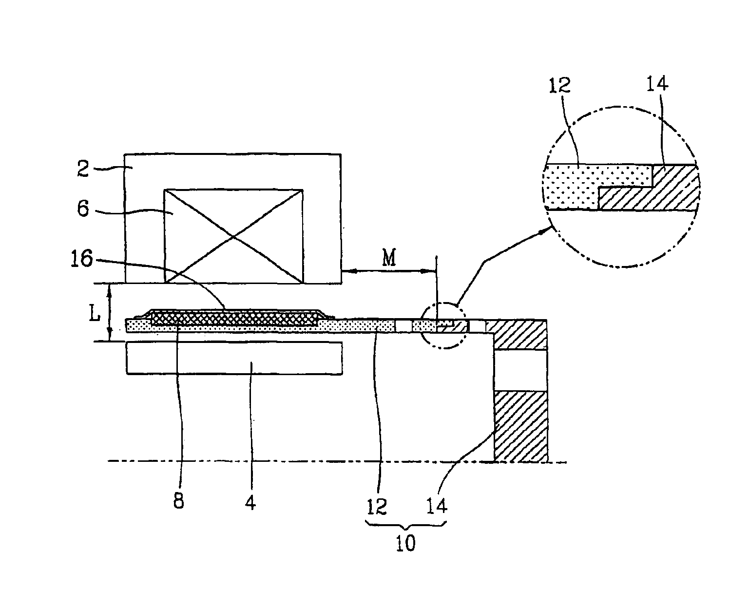
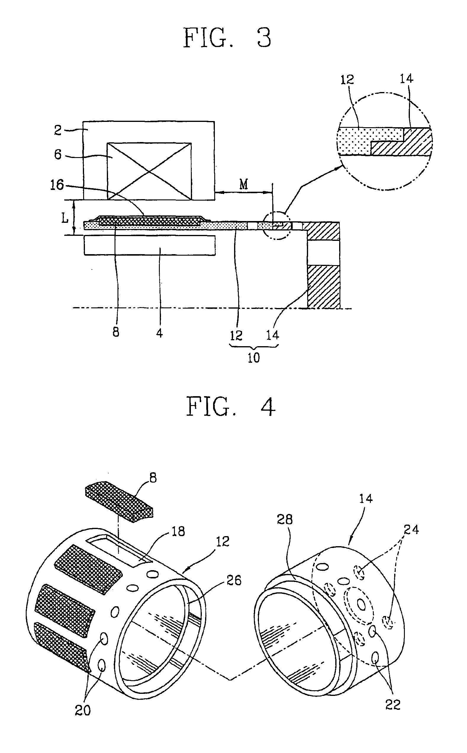
[0042]FIG. 3 is a half-sectional view of a reciprocating motor in accordance with the present invention.

[0043]The reciprocating motor of the present invention includes: an outer stator core 2 in a cylindrical form fixed at a housing (not shown); an inner stator core (4) disposed at an inner circumferential face of the outer stator 2 with a certain air gap therebetween and forming a flux between itself and the outer stator core 2; a winding coil 6 wound inside the outer stator core 2; a magnet 8 disposed to be linearly movable between the outer stator core 2 and the inner stator core 4; and a magnet frame 10 connected between the magnet 8 and an element (not ...


PUM


Abstract

A reciprocating motor is disclosed having a magnet frame (10) connected between a magnet (8) and an element to be reciprocally moved to transmit a reciprocal movement of the magnet (8) to the element, the magnet consisting of a first mounting unit (12) at which the magnet (8) is fixed and a second mounting unit (14) made of a different material with the first mounting unit (12), being connected to the first mounting (12), and with which the element is engaged. A portion of the magnet frame (10) where the magnet is fixed is made of a nonmetallic material to minimize a loss of flux generated from a winding coil (6).

Description

TECHNICAL FIELD[0001]The present invention relates to a reciprocating motor, and more particularly, to a reciprocating motor that is capable of minimizing a leakage of a magnetic field generated from a stator to thereby improve an efficiency of a motor.BACKGROUND ART[0002]In general, a reciprocating motor is constructed such that an outer stator and an inner stator are disposed with a certain interval and a rotor having a magnet is disposed between the outer stator and the inner stator so that when power is applied to a winding coil wound on the stator, the rotor is moved linearly and reciprocally owing to an interaction between the stator and the magnet.[0003]The reciprocating motor is mainly used for a reciprocating compressor, of which a piston and the rotor are connected to reciprocally move the piston.[0004]FIG. 1 is a half-sectional view of the reciprocating motor in accordance with a conventional art, and FIG. 2 is a perspective view of a rotor assembly of the reciprocating m...

Claims


Application Information

Patent Timeline
Patent Type & Authority Patents(United States)
IPC IPC(8): H02K1/06H02K1/27H02K33/00H02K1/34H02K33/16H02K1/28H02K41/02
CPCH02K1/27H02K33/16H02K1/34H02K1/28H02K33/00H02K41/02
Inventor JUNG, WON-HYUNKU, BON-CHEOL
Owner LG ELECTRONICS INC
Why Eureka
Try Eureka