
Cross-flow filter with self-regulating transmembrane pressure

a transmembrane pressure and filter technology, applied in the direction of filtering separation, moving filter element filter, separation process, etc., can solve the problems of filtration capacity and operational life loss of cross-flow filter devices, and achieve the effects of less permeation flow, small feed velocities, and more uniform transmembrane pressur

Inactive Publication Date: 2005-05-17
SARTORIUS STEDIM BIOTECH GMBH
View PDF13 Cites 21 Cited by
  • Summary
  • Abstract
  • Description
  • Claims
  • Application Information

AI Technical Summary

Benefits of technology

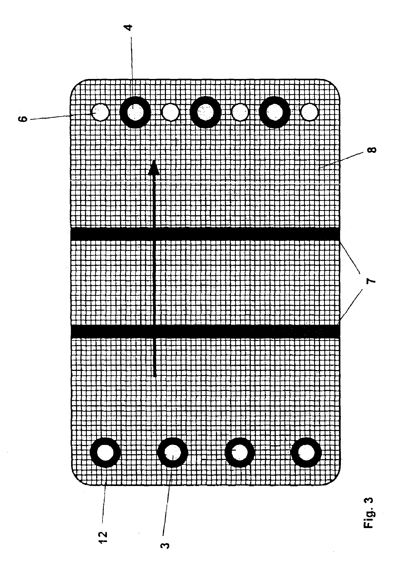
[0007]In accord with the invention, the permeate channels of a cross-flow filtration device are provided with barriers. These barriers are placed at a distance away from the permeate outlet so as to impede or block the flow of permeate, resulting in the maintenance of a more uniform transm

Problems solved by technology

Because of this, as a rule, the filtration capacity as well as the operational life of cross-flow filtration devices are diminished.

Method used


Image

  • Cross-flow filter with self-regulating transmembrane pressure
  • Cross-flow filter with self-regulating transmembrane pressure
  • Cross-flow filter with self-regulating transmembrane pressure

Examples


example 1

[0024]The above-described filter cassette was provided with spacers placed midway in the permeate channels and aligned transversely to the flow direction of the feed. Each permeate channel 1 was equipped with barrier 7 of durable elastic silicone 10 mm thick and having a height equal to the thickness of the spacer fabric (which was also the height of the permeate channel 1). Five minutes after the start of the filtration, the permeate flow was measured at 400 L / h•m2; after 90 minutes it was about 170 L / h•m2.

example 2

[0027]Filter cassettes of substantially the same design as that of Example 1 were used to conduct filtration on a 10% yeast solution with the following changes: different sized barriers were used; the cassettes were provided with 14 membranes, 7 permeate channels and 8 overflow channels; the surface area available for filtration was 0.3 m2; and the membrane had an average pore size of 0.45 μm. To determine what influence the height of the barrier (which had the same width as the permeate channel) had on permeate flow, three cassettes A, B and C were provided with variances in the barrier element as follows:[0028]in device A, one barrier was placed in each permeate channel at the mid-point, the height of which was two-thirds the height of the permeate channel;[0029]in device B, one barrier was placed in each permeate channel at the mid-point, the height of which was one-third the height of the permeate channel; and[0030]in device C, no barriers were provided.

Pressure values were PE=3...


PUM

PropertyMeasurementUnit
Thicknessaaaaaaaaaa
Pressureaaaaaaaaaa
Flow rateaaaaaaaaaa

Abstract

Cross-flow filters having improved uniformity in transmembrane pressures and consequent much greater flux are provided by the installation of barriers in permeate channels.

Description

[0001]This is a Section 371 national phase application of PCT / EP 01 / 06157, and claims priority of DE 100 28 908.8 filed Jun. 10, 2000.REFERENCE TO RELATED APPLICATIONS[0002]This disclosure claims the benefit of the filing date of International Application No. PCT / EP02 / 07403, having an international filing date of Jul. 4, 2002, which designated the United States of America, and this disclosure is the United States national stage of that international application. This disclosure further claims priority to Germany patent application 101 33 104.5, filed Jul. 12, 2001.BACKGROUND OF THE INVENTION[0003]In cross-flow filtration, a feed liquor to be filtered flows through an overflow channel, whereby the feed is directed against the surface of the filter element tangentially. The filter splits the feed into a concentrate (retentate) and a filtrate (permeate). The filter element is generally a polymeric microporous membrane with pores sized so as to be capable of ultrafiltration or microfilt...

Claims


Application Information

Patent Timeline
IPC IPC(8): B01D65/08B01D63/08B01D65/00
CPCB01D63/08B01D65/08B01D63/084B01D2321/02
Inventor GRUMMERT, ULRICH
Owner SARTORIUS STEDIM BIOTECH GMBH
Learn More