
Rotating guard for angle grinder

a technology for angle grinders and guards, which is applied in the direction of metal-working equipment, portable grinding machines, manufacturing tools, etc., can solve the problems of increasing the risk of injury

Inactive Publication Date: 2005-05-17
STIVERS J DAVID
View PDF20 Cites 63 Cited by
  • Summary
  • Abstract
  • Description
  • Claims
  • Application Information

AI Technical Summary

Benefits of technology

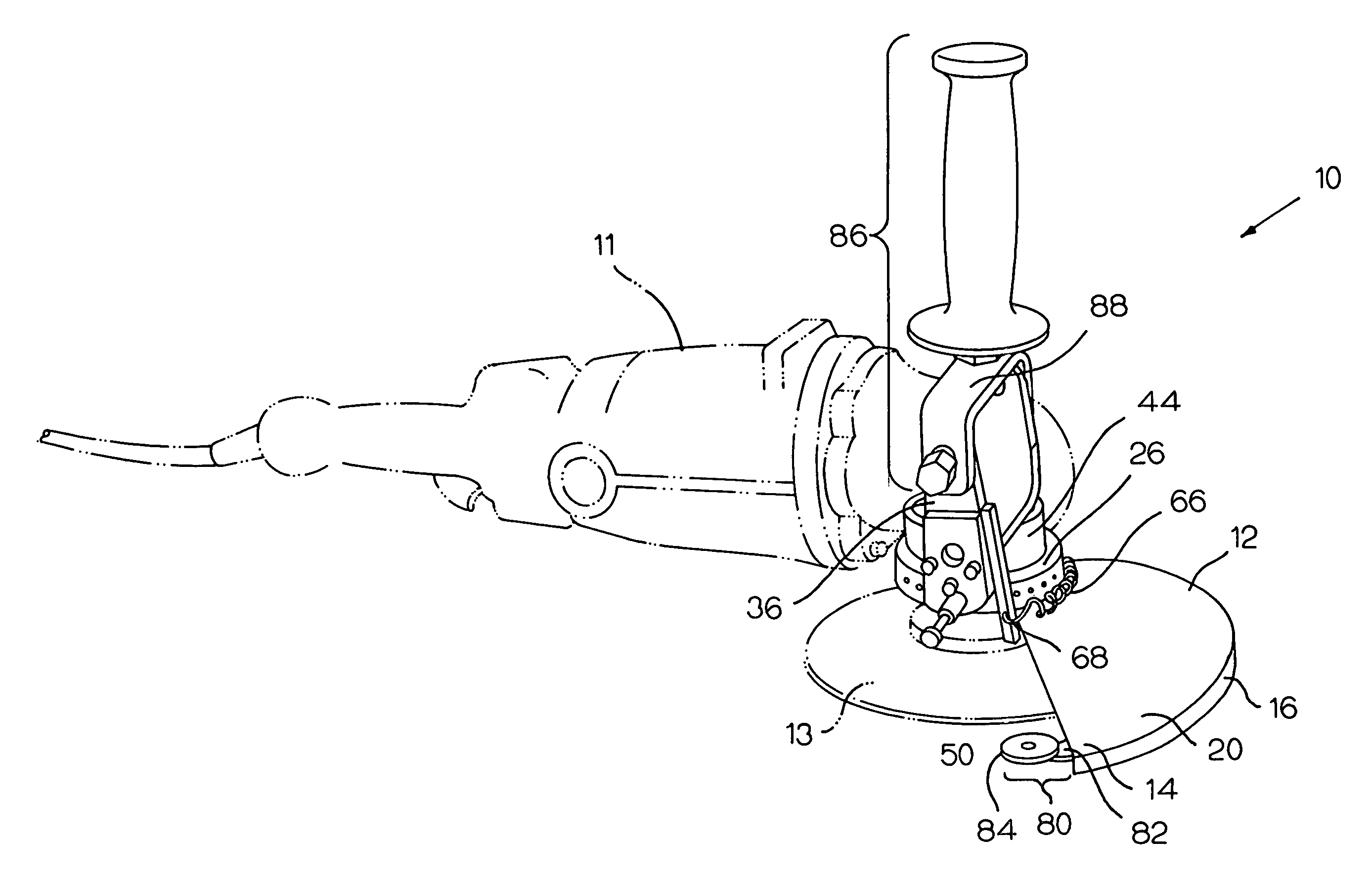
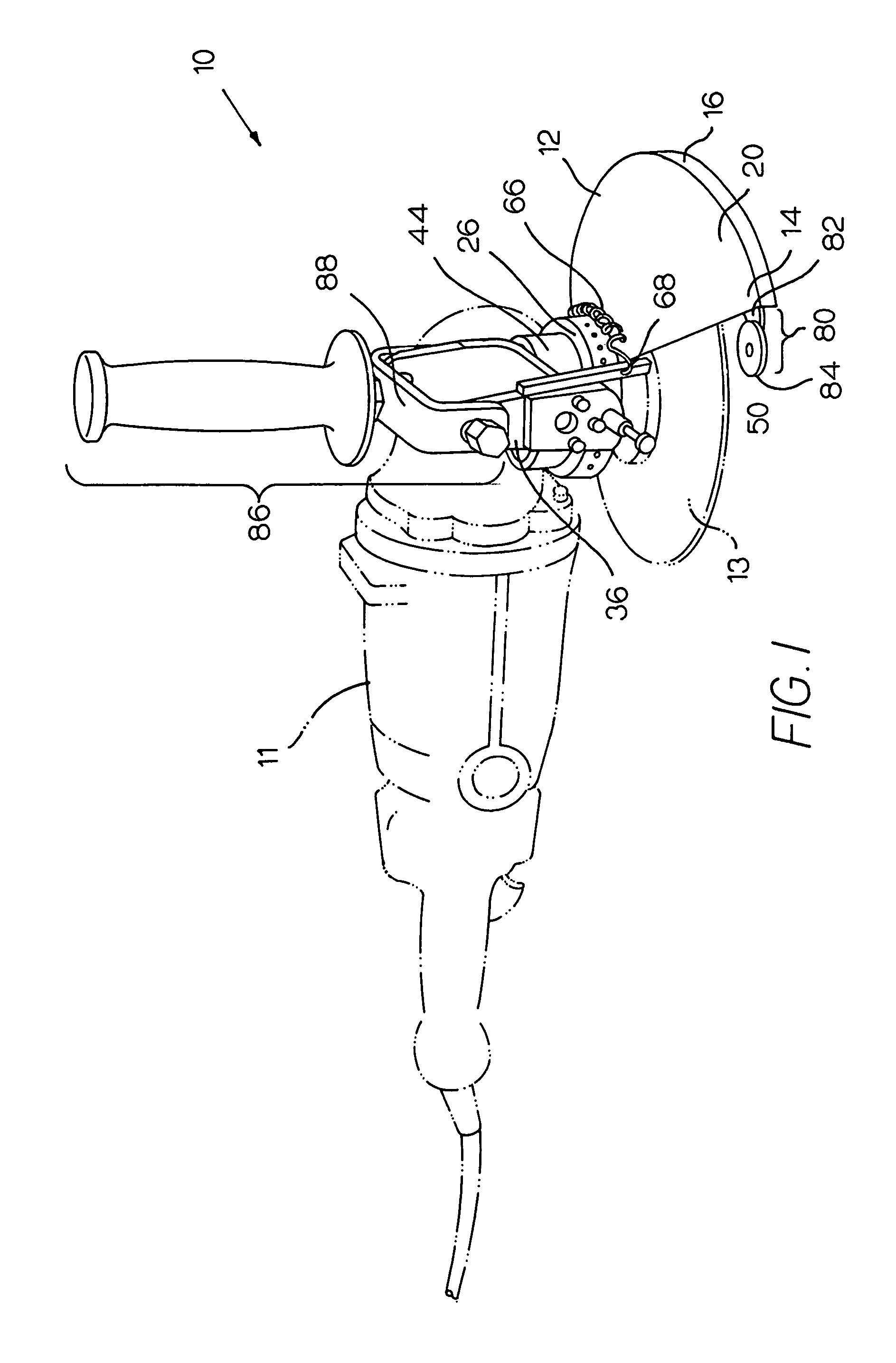
[0008]The present invention is a guard for a rotary cutting tool, such as an angle grinder, which allows for automatic adjustment of the guard relative to the cutting disc and to a workpiece. Such an automatic adjustment allows a user to cut around substantially the entire circumference of a rounded workpiece, such as a pipe, without requiring alteration of the angle at which the tool is held, repositioning by the user, or repositioning or removal of the guard. The guard of the present invention is designed to be used with a rotary cutting tool that is adapted to accept any number of implements, including for example, a cutting disc, a grinder, or a wheel brush. For purposes of simplifying the description and claims that follow, such an implement for the cutting tool is referred to as a “cutting disc.”
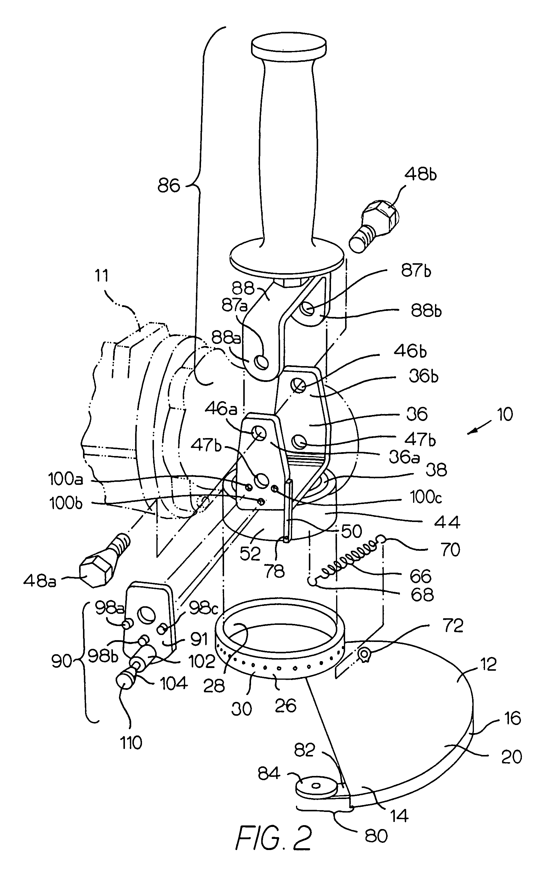
[0012]It is further preferred that the guard include at least one guide mechanism mounted near the first end of the hood. Specifically, in this preferred embodiment, the guide mechanism comprises: a guide arm affixed to the first end of the hood and a guide wheel rotatably mounted to a distal end of the guide arm. In practice, because of the biasing of the first end of the hood, it is the guide wheel that maintains substantially continuous contact with the workpiece. Because of the ability of the guide wheel to rotate, there is reduced frictional contact between the guard and the workpiece.
[0013]When using the assembled guard and cutting tool, the cutting disc is placed into contact with the workpiece, which is cut while a predetermined reference line, corresponding to the desired cut to be made, is traced with the guide wheel. As the cutting tool progresses along the outer surface of the workpiece, regardless of the angle of the surface being cut or the angle at which the cutting tool is held while cutting the workpiece, the biasing spring continually urges the hood and guide wheel affixed thereto into substantially continuous contact with the workpiece. The contact of the hood with the surface of the workpiece thus causes the hood to rotate relative to the bearing sleeve. As a result, the position of the hood relative to the cutting disc is automatically adjusted so as to continuously protect the user from accidentally contacting the disc.
[0014]As a further refinement, the preferred guard also includes a handle assembly that is attached to the bracket to improve a user's grip on the cutting tool.

Problems solved by technology

Often, the user's solution is to remove the guard, thereby increasing the risk of injury.

Method used


Image

  • Rotating guard for angle grinder
  • Rotating guard for angle grinder
  • Rotating guard for angle grinder

Examples


Embodiment Construction

[0021]The present invention is a guard for a rotary cutting tool, such as an angle grinder, which allows for automatic adjustment of the guard relative to the cutting disc and to a workpiece. Such an automatic adjustment allows a user to cut around substantially the entire circumference of a rounded workpiece, such as a pipe, without requiring alteration of the angle at which the tool is held, repositioning by the user, or repositioning or removal of the guard. The guard of the present invention is designed to be used with a rotary cutting tool that is adapted to accept any number of implements, including for example, a cutting disc, a grinder, or a wheel brush. As mentioned above, for purposes of simplifying the description and claims that follow, such an implement for the cutting tool is referred to as a “cutting disc.”

[0022]Referring first to FIGS. 1 and 2, a preferred guard 10 made in accordance with the present invention includes a hood 12 for enclosing a portion of a cutting d...


PUM


Abstract

A guard for a rotary cutting tool allows for automatic adjustment of the guard relative to the cutting disc and to a workpiece. Such an automatic adjustment allows a user to cut around substantially the entire circumference of a rounded workpiece, such as a pipe, without requiring alteration of the angle at which the tool is held, repositioning by the user, or repositioning or removal of the guard. The guard includes a bracket for mounting the guard to the rotary cutting tool, a hood mounted to the bracket and enclosing a portion of the cutting disc, and a spring for biasing one end of the hood into substantially continuous contact with the workpiece during operation of the rotary cutting tool.

Description

CROSS REFERENCE TO RELATED APPLICATION[0001]This application claims priority to U.S. Provisional Application Ser. No. 60 / 352,109 filed Jan. 24, 2002 and relates to a guard for a rotary cutting tool. The entire disclosure contained in U.S. Provisional Application Ser. No. 60 / 352,109 is incorporated herein by this reference.FIELD OF THE INVENTION[0002]This invention relates generally to the field of guards for power tools. In particular, the present invention relates to a guard for a rotary cutting tool, such as an angle grinder, which allows for automatic adjustment of the guard relative to a workpiece. Such an automatic adjustment allows a user to cut around substantially the entire circumference of a rounded workpiece, such as a pipe, without requiring alteration of the angle at which the tool is held, repositioning by the user, or repositioning or removal of the guard.BACKGROUND OF THE INVENTION[0003]Various types of guards for rotary cutting tools, such as angle grinder, are disc...

Claims


Application Information

Patent Timeline
IPC IPC(8): B24B23/02B24B23/00B24B55/05B24B55/00
CPCB24B55/052B24B23/028
Inventor STIVERS, J. DAVID
Owner STIVERS J DAVID
Learn More