EMI shielded adapter for fiber optic connector systems

a technology of emi shielding and fiber optic connectors, applied in the direction of coupling device connections, electrical apparatus casings/cabinets/drawers, instruments, etc., can solve the problems of generating emi noise, other electronic equipment used in conjunction with optical components may be sensitive to emi noise, and mounting configuration may be susceptible to emi leakage, etc., to reduce the area of possible leakage, increase the emi shielding performance of the adapter

Inactive Publication Date: 2005-05-10
TYCO ELECTRONICS LOGISTICS AG (CH)
View PDF14 Cites 19 Cited by
  • Summary
  • Abstract
  • Description
  • Claims
  • Application Information

AI Technical Summary

Benefits of technology

[0008]The present invention provides for unobtrusive EMI shielding for an adapter by using an electrically-conductive wall within the adapter to channel EMI emissions to ground. In a preferred embodiment, the adapter comprises: (a) an elongated housing having a first and second end and defining a first passageway extending axially from the first end toward the second end, and a second passageway extending axially from the second end toward the first end, each passageway configured to receive an optical connector plug; (b) an electrically-conductive wall traversing the adapter between the first and second passageways, the wall being sized to cover a substantial portion of the opening when the adapter is mounted to the chassis; and (c) at least one portion of the wall extending outside of the housing to electrically couple with the chassis of the computer system when the adapter is mounted to the chassis forming an electrically-conductive path between a point on the wall and the chassis. Preferably, this portion extends around the entire perimeter of the adapter resulting in a continuous or nearly continuous ring of contact when the adapter is mounted to the chassis. Having an electrical coupling around the perimeter increases the EMI shielding performance of the adapter by reducing areas of possible leakage and ensures the shortest possible path to ground from any point on the electrically-conductive wall.
[0009]The adapter in accordance with the present invention provides several advantages over the prior art. First, it reduces EMI leakage in and out of the shielded chassis through the hole where the adapter is mounted. This is accomplished without the need for a space consuming EMI boot inside the chassis. Additionally, it forms an electrical coupling with the chassis along a substantial portion of the perimeter of its surface that contacts the chassis faceplate. This minimizes the grounding path length for any point on the electrically-conductive wall, thereby reducing the potential for the electrically-conductive wall to radiate EMI. Aside from offering improved EMI performance, the adapter of the present invention reduces assembly time and expense by eliminating the need to install an EMI boot over the installed adapter. The adapter of the present invention is installed using the same procedure and tools as a conventional adapter. Thus, the adapter of the present invention offers the benefits of a conventional adapter plus improved EMI shielding.

Problems solved by technology

Although effective in securing an adapter to a chassis, this mounting configuration may be susceptible to EMI leakage.
Although EMI does not affect optical components, other electronic equipment used in conjunction with optical components may be sensitive to EMI noise or may generate EMI noise.
Unfortunately, adapter openings in the chassis are sources of EMI leakage.
Furthermore, a chassis will typically have a series of openings to accommodate a multitude of adapters thus compounding the EMI leakage problem.
Although this provides reduced EMI leakage, it requires space within the chassis to accommodate the EMI boot.
This is problematic since space within the chassis is usually limited.
Furthermore, as the complexity of equipment increases to accommodate more fibers, space within the chassis will become even more precious.

Method used


Image

  • EMI shielded adapter for fiber optic connector systems
  • EMI shielded adapter for fiber optic connector systems
  • EMI shielded adapter for fiber optic connector systems

Examples


Embodiment Construction

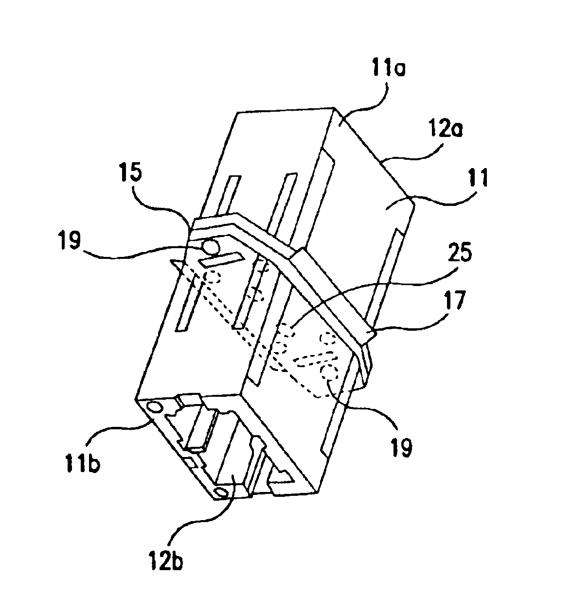
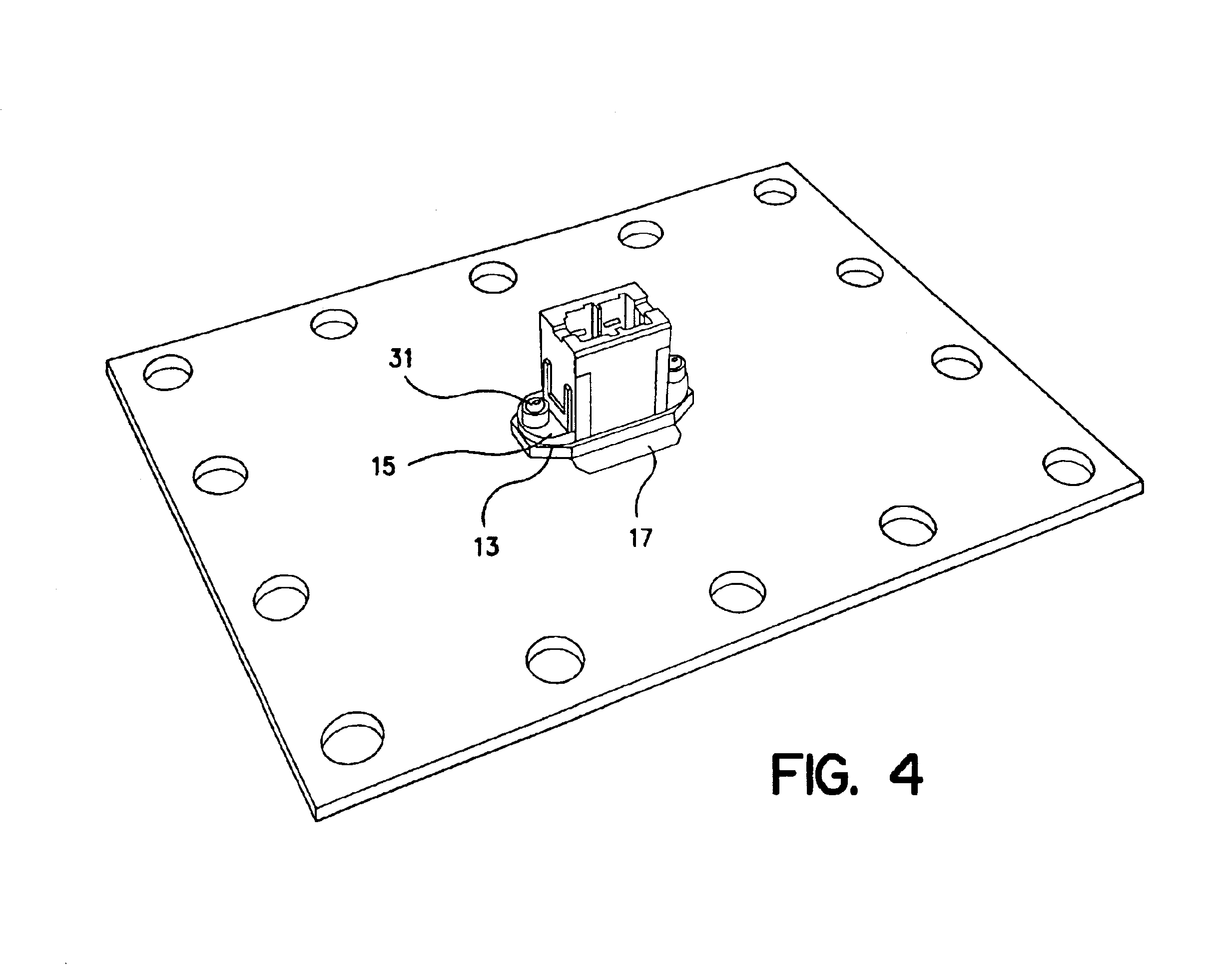
[0014]The present invention provides for an adapter (as defined above) which comprises internal EMI shielding to reduce the EMI emissions passing in or out of a chassis on which the adapter is mounted. The adapter of the present invention is described herein with respect to the MU duplex adapter. It should be understood, however, that the present invention may be practiced with adapters of any known or later-developed connector systems, including, for example, the MPO connector system, Lightray MPX® connector system (Tyco Electronics Corporation, Harrisburg, Pa.), LC connector system, SC connector system, FC connector system, and MT-RJ connector system. The present invention is discussed below using an MU connector system as the preferred embodiment. It should be understood, however, that the invention is not limited to this connector type and is applicable to all connector systems utilizing an adapter portion. Furthermore, it should be understood, that the adapter of the present in...


PUM


Abstract

An adapter using an electrically-conductive wall within the adapter to channel EMI emissions to ground. In a preferred embodiment, the adapter comprises: (a) an elongated housing having a first and second end and defining a first passageway extending axially from the first end toward the second end, and a second passageway extending axially from the second end toward the first end, each passageway configured to receive an optical connector plug; (b) an electrically-conductive wall traversing the adapter between the first and second passageways, the wall being sized to cover a substantial portion of the opening when the adapter is mounted to the chassis; and (c) at least one portion of the wall extending outside of the housing to electrically couple with the chassis of the computer system when the adapter is mounted to the chassis forming an electrically-conductive path between a point on the wall and the chassis.

Description

REFERENCE TO RELATED APPLICATION[0001]This applications claims priority to U.S. Provisional Application 60 / 341,556, filed Dec. 14, 2001, which is hereby incorporated by reference.FIELD OF THE INVENTION[0002]The present invention relates generally to adapters for the use with fiber optics, and, more specifically, to an adapter having electromagnetic interference (EMI) shielding.BACKGROUND OF THE INVENTION[0003]In the optical fiber field, there is a need to connect the optical transmission path of a fiber or device to that of another fiber or device. Often this connection is effected by inserting a plug into an adapter. As used herein, the term “adapter” refers to any structure that facilitates fiber / fiber, device / fiber and device / device interconnections. An adapter generally comprises a housing, or portion of a housing, having a port which is configured to receive and hold a plug to facilitate the plug's optical connection with another plug or other device which connected to the adap...

Claims


Application Information

Patent Timeline
Patent Type & Authority Patents(United States)
IPC IPC(8): G02B6/38
CPCG02B6/381G02B6/3825G02B6/3897
Inventor HULTERMANS, ANTONIUSELENBAAS, JACOB ARIESHIPE, JEFFREY DEANHOPKINS, ERIC JAMES
Owner TYCO ELECTRONICS LOGISTICS AG (CH)
Why Eureka
Try Eureka