
Methods and apparatus for frequency shifting polarization mode dispersion spectra

a technology of polarization mode and polarization mode, applied in the field of frequency shifting an optical filter spectra, can solve the problems of asymmetry of fiber-optic strands, potential for prolonged degradation of data transmission, and complicated polarization-dependent effects

Inactive Publication Date: 2005-05-10
NEW RIDGE TECH
View PDF29 Cites 12 Cited by
  • Summary
  • Abstract
  • Description
  • Claims
  • Application Information

AI Technical Summary

Benefits of technology

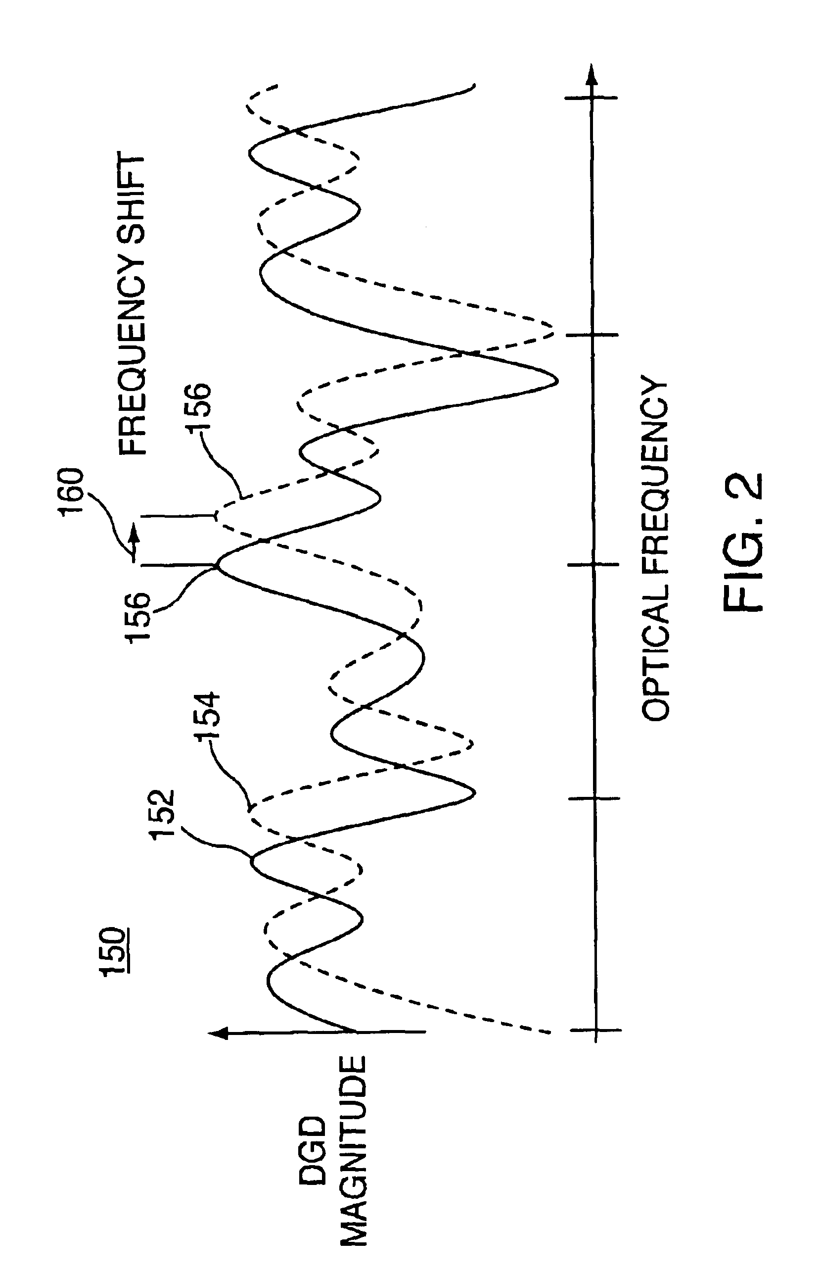
[0013]It is also an object of the present invention to provide methods and apparatus to continuously frequency shift a frequency-dependent PMD spectrum without substantially changing the spectrum's shape.

Problems solved by technology

The primary cause of PMD is the asymmetry of the fiber-optic strand.
Environmental changes are dynamic and statistical in nature, and are believed to result in PMD changes that can last for variable periods of time and vary with wavelength, with the potential for prolonged degradation of data transmission.
When the transmission path is long, these localized birefringent sections can combine to yield a particularly complicated polarization-dependent effect.
Mechanical stress on the fiber resulting from cabling and installation can also cause the fiber to suffer stress-induced birefringence.
In many cases, however, the center frequency of the optical signal being tested may not be properly aligned with the PMD spectrum generated by the emulator.
Unfortunately, this misalignment reduces the predictability and repeatability of the tests being performed.
Because a conventional PMD emulator cannot controllably “frequency shift” its spectrum to accommodate for the misalignment, those attempting to evaluate the PMD response of receivers and other equipment are generally forced to test undesirable and unpredictable PMD states.
In contrast to PMD emulators, PMD compensators generally include only one or two birefringent sections, but such a small number of sections greatly limits the range of achievable PMD states.
Unfortunately, PMD spectra generated with more than two sections are difficult to control, subject to misalignment, and are highly frequency dependent.
Although this independence is desirable from an alignment perspective, the limited number of stages provides a limited number of PMD states.
Therefore, three or more stages are desirable to achieve a large number of PMD states, but control of devices with three or more stages can be highly unpredictable and susceptible to misalignment.

Method used


Image

  • Methods and apparatus for frequency shifting polarization mode dispersion spectra
  • Methods and apparatus for frequency shifting polarization mode dispersion spectra
  • Methods and apparatus for frequency shifting polarization mode dispersion spectra

Examples


Embodiment Construction

[0060]PMD is an optical property that can be generated by a concatenation of two or more birefringent elements in succession. To frequency shift a PMD spectrum without changing its shape, optical retardation of each of the birefringent elements should be changed in coordination. The amount of optical retardation change required for a birefringent element is determined by the differential group delay of the element. Accordingly, the optical retardation change for each birefringent element can be different or can be the same. In either case, coordinated control of optical retardation can be used to frequency shift a PMD spectrum without changing its shape.

[0061]FIG. 1 shows illustrative PMD generator and phase shifter apparatus 100. Input optical beam 101 propagates through all optical elements of apparatus 100 to generate output optical beam 102 having a certain amount of PMD. Each of birefringent stages 104, 106, . . . , and 108 is capable of generating an amount of differential gro...


PUM


Abstract

A polarization mode dispersion generator for generating polarization mode dispersion (“PMD”) spectra is provided. The generator includes a plurality of birefringent stages, each stage including a differential group delay (“DGD”) element and a phase-shifting element. The generator is capable of inducing an amount of polarization mode-mixing between at least one adjacent pair of stages. The shape of a PMD spectrum can be preserved while frequency shifting the spectrum in either direction. Alternatively, the shape of the PMD spectrum can be changed without frequency shifting.

Description

CROSS-REFERENCE TO RELATED APPLICATIONS[0001]This claims the benefit of U.S. Provisional Patent Application No. 60 / 251,765, filed Dec. 7, 2000, which is hereby incorporated by reference herein in its entirety.FIELD OF THE INVENTION[0002]This invention relates to frequency shifting an optical filter's spectra, and more particularly to continuously frequency shifting polarization mode dispersion spectra.BACKGROUND OF THE INVENTION[0003]Polarization mode dispersion (hereinafter, “PMD”) is caused by variations in birefringence along the optical path that causes the orthogonal optical signal polarization modes to propagate at different velocities. The primary cause of PMD is the asymmetry of the fiber-optic strand. Fiber asymmetry may be inherent in the fiber from the manufacturing process, or it may be a result of mechanical stress on the deployed fiber. Environmental changes are dynamic and statistical in nature, and are believed to result in PMD changes that can last for variable peri...

Claims


Application Information

Patent Timeline
IPC IPC(8): G02F1/01G02B6/34H04B10/18
CPCG02B6/278H04B10/2569G02F1/0136
Inventor DAMASK, JAY N.
Owner NEW RIDGE TECH
Learn More