Antenna

an exciter and antenna technology, applied in the field of antennas, can solve the problems of destroying the windows along with the antennas, destroying the antennas, and not using discone-type exciters, etc., and achieve the effect of low profil

Inactive Publication Date: 2005-05-10
COCOMO MB COMM INC
View PDF33 Cites 10 Cited by
  • Summary
  • Abstract
  • Description
  • Claims
  • Application Information

AI Technical Summary

Benefits of technology

[0022]A primary advantage of the present invention is that a low-cost, low-profile, effective antenna is provided.
[0023]Another advantage of the present invention is that the vehicle may be used as a direct radiator for the antenna.
[0024]Other objects, advantages and novel features, and further scope of applicability of the present invention will be set forth in part in the detailed description to follow, taken in conjunction with the accompanying drawings, and in part will become apparent to those skilled in the art upon examination of the following, or may be learned by practice of the invention. The objects and advantages of the invention may be realized and attained by means of the instrumentalities and combinations particularly pointed out in the appended claims.
[0025]The accompanying drawings, which are incorporated into and form a part of the specification, illustrate one or more embodiments of the present invention and, together with the description, serve to explain the principles of the invention. The drawings are only for the purpose of illustrating one or more preferred embodiments of the invention and are not to be construed as limiting the invention. In the drawings:
[0026]FIG. 1 is a side section view of the preferred embodiment of the present invention, showing a modified discone exciter;
[0027]FIG. 2 is a diagram of the evolution of the present invention;

Problems solved by technology

Now that automobile connectivity is often used for emergency services, the survival of the antennas becomes a paramount issue.
Unfortunately, one of the first things to be destroyed is the windows along with their antennas.
In a severe accident, the automobile may often be upside down with the under-chassis pointed skyward.
The problem of providing a solution for a survivable antenna connectivity for vehicles has presented a major challenge to engineers and technicians in the automotive industry.
None of these patents disclose the use of a discone-type of exciter.

Method used


Image

  • Antenna
  • Antenna
  • Antenna

Examples


example 1

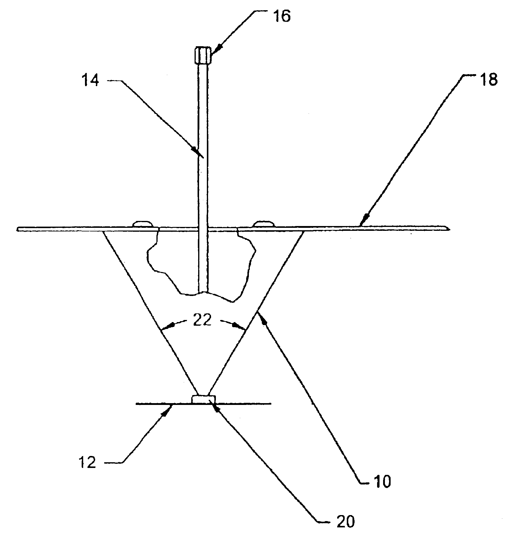
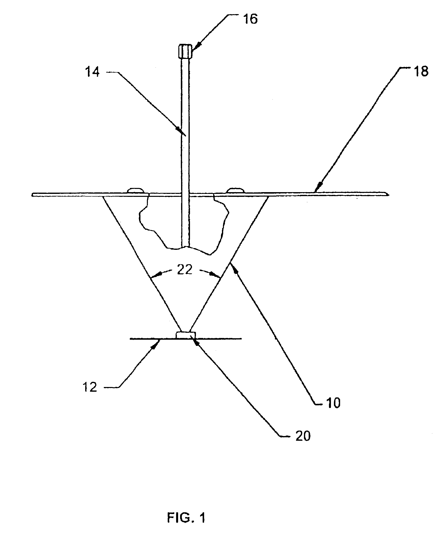
[0069]Initial data was first taken on a free space range and included the ground plane shown in FIG. 1. The match of the antenna is shown in FIG. 6. The Voltage Standing Wave Ratio (VSWR) is less than 2:1 from 600 MHz to 1800 MHz. The VSWR is less than 3:1 from 580 MHz to 2 GHz. The azimuth and elevation patterns are shown in FIGS. of 7 through 11. The azimuth patterns are omnidirectional with 1 dB from 800 MHZ to 1.5 GHz and less than 2 dB to 1.9 GHz. The elevation patterns are typical cardiods over the entire band. The 0 degree reference was at the base of the ground plane. The results were considered adequate and the next phase was the testing of an automobile mounted antenna.

example 2

[0070]The FIG. 1 antenna was positioned 9″ from the centerline of the front bumper of an automobile. The measured return loss is shown in FIG. 14 and measured VSWR is shown in FIG. 13. The VSWR is less than 3 to 1 from approximately 620 MHz to 2 GHz. The effect of VSWR on the vehicle is quite small as shown in the comparison of FIG. 6.

[0071]Measured patterns are shown in FIGS. 14 through 16 for frequencies of 850 MHz, 1575 MHz and 1850 MHz and at elevation heights of 1, 3 and 5 feet (the transmitter was located approximately 10 feet away from the vehicle). The 850 MHz frequency generally provided the same response, however, the front lobe was typically 20 dB stronger than the rear lobe. The 1575 MHz frequency provided better coverage for heights of 1-3 feet above the ground and 10 feet away, but was reduced at an elevation of 5 feet. At 1575 MHz the front lobe was typically 20 dB stronger than the rear lobe. At 1850 MHz the front lobe was typically 20 dB stronger than the rear lobe ...

example 3

[0072]The relative gains of an analog cell phone stub antenna, GPS stub antenna and PCS stub antenna are shown in FIGS. 18 through 20 compared with the antenna of the present invention. The antenna of the present invention was stronger over most of the region except for the rearward direction. The stub antennas for each unit were located on the console between the driver and passenger seats. The stub antennas were mounted vertically to match the testing antenna polarization. The test range layout is shown in FIG. 21.


PUM


Abstract

An antenna system, particularly for vehicles. A discone-type antenna is preferably utilized for frequencies outside the vehicle. At various frequencies, either or both the antenna and the vehicle serve as exciters.

Description

CROSS-REFERENCE TO RELATED APPLICATIONS[0001]This application is a continuation-in-part application of U.S. patent application Ser. No. 09 / 724,535, entitled “In-Vehicle Exciter”, to Chadwick, filed on Nov. 27, 2000 now abandoned, and U.S. patent application Ser. No. 10 / 160,747, entitled “Exciter System and Excitation Methods for Communications Within and Very Near to Vehicles”, to Chadwick, et al., filed on May 30, 2002 now U.S. Pat. No. 6,600,896, and the specifications thereof are incorporated herein by reference.BACKGROUND OF THE INVENTION[0002]1. Field of the Invention (Technical Field)[0003]The present invention relates to an antenna and exciter systems for vehicles, such as automobiles, trucks, trains, buses, boats and aircraft.[0004]2. Description of Related Art[0005]Note that the following discussion refers to a number of publications by author(s) and year of publication, and that due to recent publication dates certain publications are not to be considered as prior art vis-...

Claims


Application Information

Patent Timeline
Patent Type & Authority Patents(United States)
IPC IPC(8): H01Q13/00H01Q1/32H01QH01Q1/28H01Q1/34H01Q9/28
CPCH01Q1/28H01Q1/3275H01Q9/28H01Q1/34H01Q1/3291H01Q13/00H01Q1/32H01Q1/12
Inventor CHADWICK, GEORGE G.
Owner COCOMO MB COMM INC
Why Eureka
Try Eureka