
Packaging for containing and dispensing large quantities of wire

a technology for welding wire and packaging, which is applied in the direction of transportation and packaging, tray containers, manufacturing tools, etc., can solve the problems of significant downtime, large amount of wire distortion and tangling, and adversely affect the welding process, and achieves smooth and uninterrupted payout of welding wire from the package, and without tangling. , the effect of easy transportation and other manipulation

Inactive Publication Date: 2005-05-10
LINCOLN GLOBAL INC
View PDF42 Cites 49 Cited by
  • Summary
  • Abstract
  • Description
  • Claims
  • Application Information

AI Technical Summary

Benefits of technology

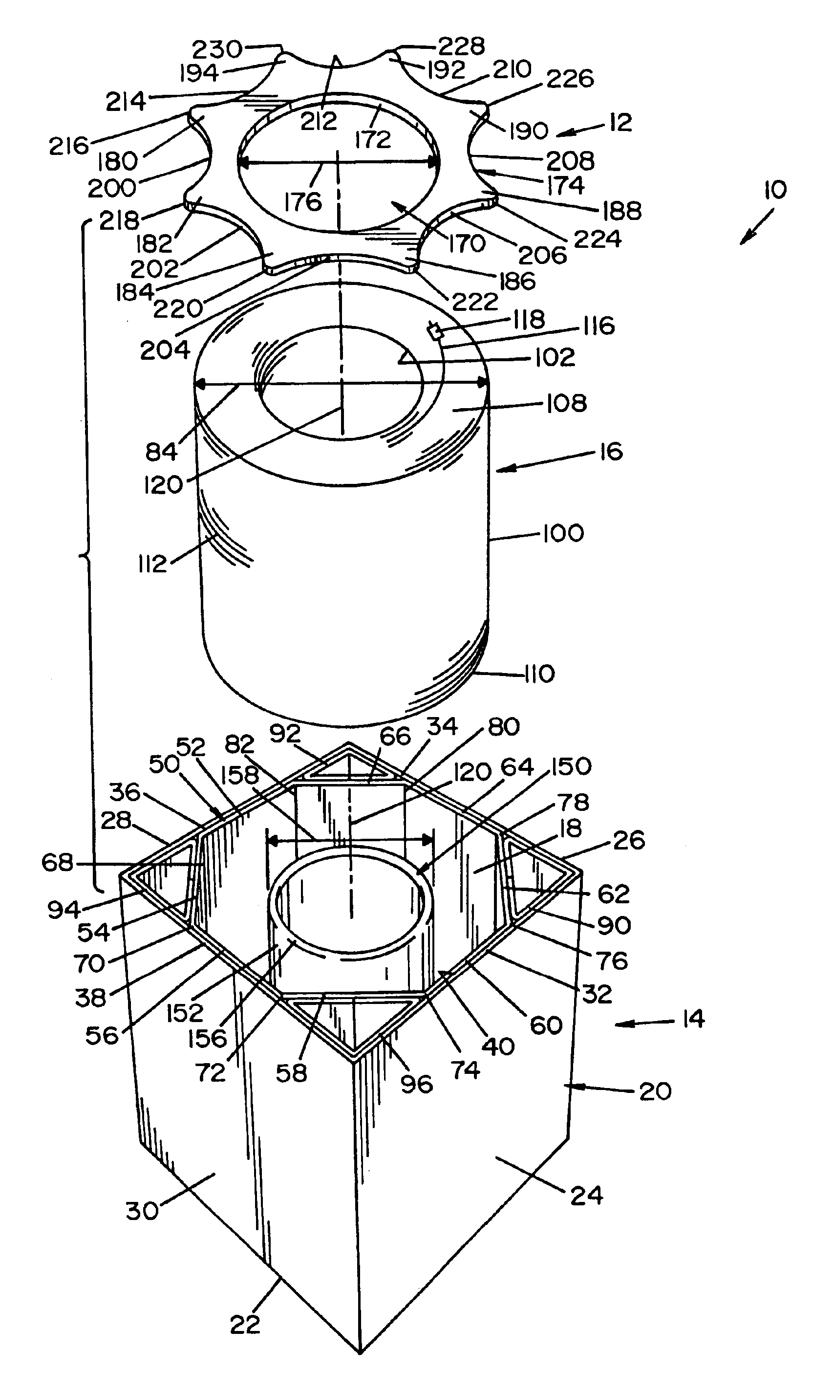
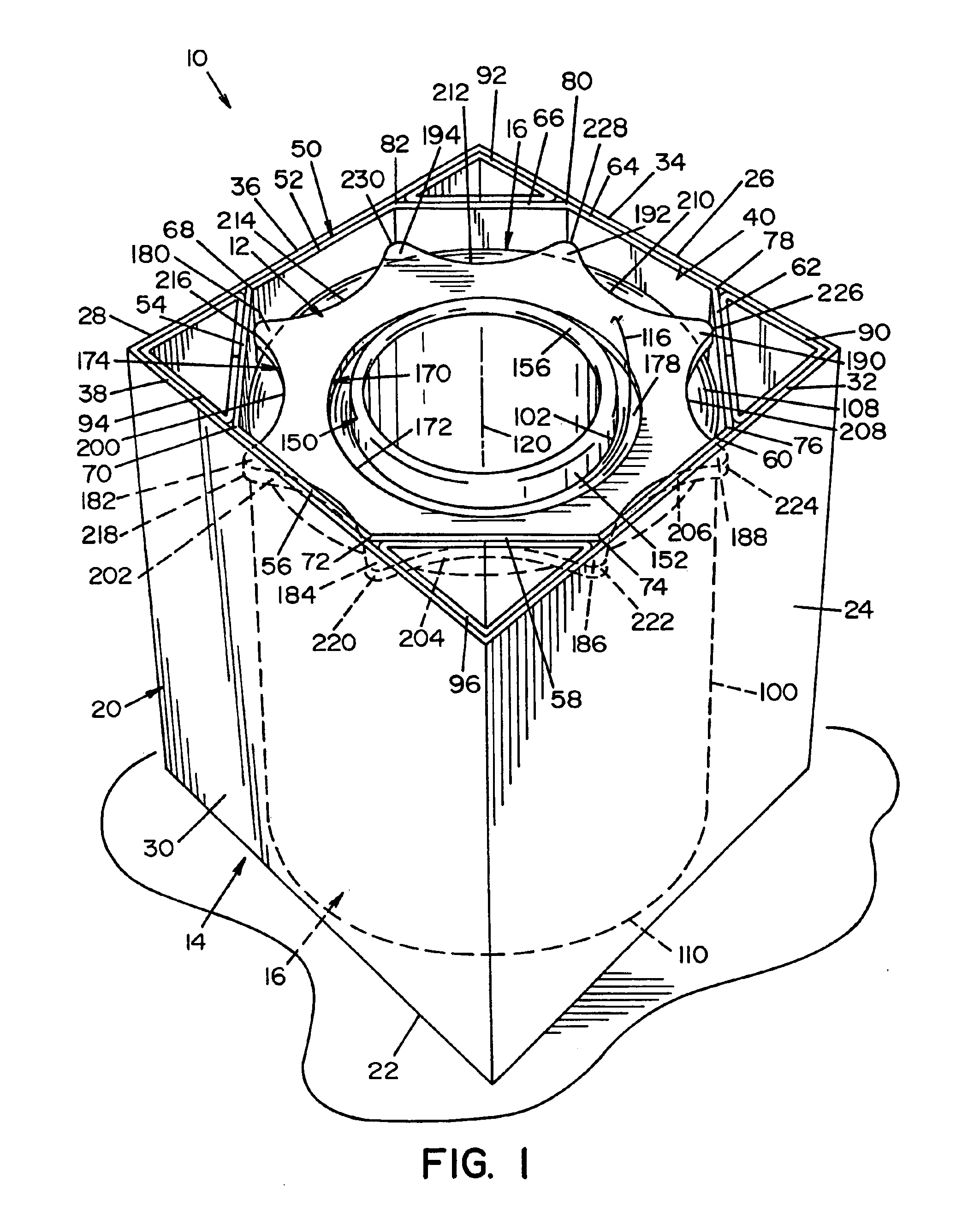
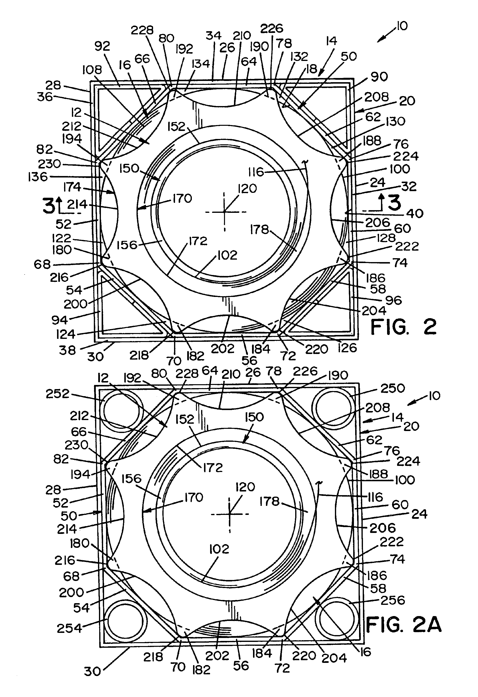
[0011]In accordance with the present invention, provided is a welding wire package is provided which includes a retainer ring that interacts with the inner liner of the welding wire package to control the payout of the welding wire and which ring and package are easily disposed of once the welding wire of the package has been consumed. In this respect, a package in accordance with the present invention includes a retainer ring conforming to the inner walls of the package and including portions that extend radially beyond the outer diameter of the wire coil convolutions for minimizing or eliminating the frictional interengagement between the retainer ring and the inner walls of the package. By including portions which extend beyond the outer diameter of the wire coil, the retainer ring advantageously prevents convolutions from springing outside of the ring without necessitating excessive frictional interengagement between the retainer ring and the inner walls of the package.
[0012]Preferably, the retainer ring according to the present invention is used in connection with an inner liner having an octagonal cross-sectional configuration, wherein the extending portions of the retainer ring extend beyond the outer diameter of the wire coil into the corners of the octagonal liner. By extending beyond the outer diameter of the wire coil, frictional interengagement with the inner liner is not required and the retainer ring is allowed to freely descend downwardly within the inner liner as the wire is payed out of the package. The lack of frictional engagement allows a lighter and a more disposable retainer ring to be utilized which is inexpensive to manufacture while still being effective in controlling the payout of the welding wire. When used in connection with a disposable cardboard-style box package, the arrangement makes disposal of the packaging after use less costly. This is especially advantageous in high volume welding processes such as for automated or semi-automated welding.
[0013]Another aspect of the present invention is that the engagement points between the wire coil and the inner liner are spaced from the engagement points between the retainer ring and the inner liner. Therefore, the forces produced by the convolutions of the coiled wire are controlled by the inner liner and are spaced from the extensions of the retainer ring which further prevents the convolution from passing outside the ring. In this respect, whether an octagonal liner is used, or merely a square box, or even a cylindrical container with supports, the outer diameter of the welding wire interengages with the inner surfaces of the welding wire package at predetermined points equally spaced within the welding wire package. With respect to octagonal inner liners, the outer diameters of the convolutions interengage the vertically extending planar walls of the inner liner generally at their centers. Conversely, the retainer ring extensions engage the inner liner at one or more of the corners between the vertically extending walls. As a result, even though the wire can cause deformation of the central portions of the vertically extending inner liner wall, the extensions on the retainer ring are spaced therefrom and are not affected. Therefore, the retainer ring according to the present invention does not have to interengage with the inner liner to such a degree to account for the potential deformation caused thereto by the wire coil which further reduces the friction therebetween. In addition, by including an inwardly extending edge portion between the extensions, friction is further reduced and the position of the retainer ring is not influenced by the deformation of the liner caused by the outward force produced by the wire coil.

Problems solved by technology

Furthermore, welding applications wherein large quantities of welding wire are consumed necessitate welding wire packages which contain large quantities of a continuous welding wire.
It is well known that wire has a tendency to seek a predetermined natural condition which can adversely affect the welding process.
To help in this respect, the manufacturers of welding wire produce a wire having natural cast wherein if a segment of the wire was laid on the floor, the natural shape of the wire would be essentially a straight line; however, in order to package large quantities of the wire, the wire is coiled into the package which can produce a significant amount of wire distortion and tangling as the wire is dispensed from the package.
Both tangling or breaking of the welding wire can cause significant down time while the damaged wire is removed and the wire is re-fed into the wire feeder.
However, when the welding wire payes out of the package, the walls of the package loose their influence on the wire and the wire is forced toward its natural cast.
This causes the portion of the wire which is being withdrawn from the package to loosen and tend to spring back into the package thereby interfering and possibly becoming tangled with other convolutions of wire.
However, by having frictional engagement between the retainer ring and the inner container walls drag is introduced which adversely reduces the downward force of the retainer ring on the wire coil can and can adversely jam the retainer ring above the wire coil, thereby reducing its control on the wire payout.
While rigid packages can advantageously reduce the tendency of coil shifting within the package during shipment and use, and enhance the stackability of the package, they can be difficult and expensive to dispose of.

Method used


Image

  • Packaging for containing and dispensing large quantities of wire
  • Packaging for containing and dispensing large quantities of wire
  • Packaging for containing and dispensing large quantities of wire

Examples


Embodiment Construction

[0030]Referring now in greater detail to the drawings wherein the showings are for the purpose of illustrating preferred embodiments of the invention only, and not for the purpose of limiting the invention, FIGS. 1, 2, 3, and 4 show a welding wire package 10 which includes a retainer ring 12 and a package portion 14. Package portion 14 is a box product made from cardboard or the like and is shaped to receive a coil of wire 16 in a coil receiving recess 18. Package portion 14 has an outer carton 20 with a square bottom wall 22 and four side panels 24, 26, 28, and 30 which extend vertically from bottom wall 22 an equal distance. Each side panel has a top edge 32, 34, 36, and 38 respectively, forming a square top opening 40. While not shown, it should be noted that any known method can be used to cover or seal top opening 40 for shipping. This can include cardboard flaps which extend from top edges 32, 34, 36, and 38 or a separate top panel which can be secured to the outer carton 20.

[...


PUM

PropertyMeasurementUnit
Angleaaaaaaaaaa
Diameteraaaaaaaaaa

Abstract

A package for containing and dispensing wire from a coil of wire having an outer surface, an inner surface, and a top and bottom defining a coil height comprising an outer carton having a rectangular bottom wall and four side panels extending upwardly from the bottom wall. The package further includes an octagonal inner liner having eight walls and wherein every other wall engages a portion of one of the side panels of the outer carton. The package has a planar retainer ring which engages the top of the wire coil and which has an opening forming an inner edge and an outer periphery comprising a plurality of nodes extending radially outwardly beyond the outer surface of the wire coil. Adjacent nodes are connected by a node edge extending inwardly across the outer surface of the coil, and at least one of the nodes interengages with the liner at a corner between adjacent walls thereof to prevent the retainer ring from rotating relative to the inner liner and to prevent the wire from passing the outer peripheral edge of the retainer ring.

Description

CROSS-REFERENCE TO RELATED APPLICATION[0001]This application is a divisional of U.S. application Ser. No. 09 / 944,565 filed Sep. 4, 2001, now U.S. Pat. No. 6,648,141.[0002]This invention relates to the art of dispensing wire and, more particularly to a package for containing and dispensing large quantities of a continuous wire without tangling.INCORPORATION BY REFERENCE[0003]The present invention relates to feeding large quantities of a continuous wire from a container to a welding operation wherein the wire must be fed to the welding operation without tangling or interruption. Such containers are known in the art and are generally shown and described in Cooper U.S. Pat. No. 5,277,314; Cooper U.S. Pat. No. 5,819,934; Chung U.S. Pat. No. 5,746,380; Kawasaki U.S. Pat. No. 4,869,367 and Gelmetti U.S. Pat. No. 5,494,160. These patents are incorporated by reference herein as background information illustrating packages for containing and dispensing large quantities of wire. Further, these...

Claims


Application Information

Patent Timeline
IPC IPC(8): B65H49/00B65H49/08B65D85/04B23K9/133B23K9/32B65H49/06B65H57/18B65H59/06
CPCB65H49/08B23K9/32
Inventor LAND, JAMES T.
Owner LINCOLN GLOBAL INC
Learn More