
Waveguide device and optical transfer system for directing light to an image plane

a waveguide device and optical transfer technology, applied in the field of light transfer devices and systems, can solve the problems of increasing the complexity of mechanically mounting each component of the system, reducing the overall cost of the system, and reducing the efficiency of the system, so as to achieve efficient and effective light transmission

Inactive Publication Date: 2005-05-03
EASTMAN KODAK CO
View PDF168 Cites 16 Cited by
  • Summary
  • Abstract
  • Description
  • Claims
  • Application Information

AI Technical Summary

Benefits of technology

The present invention is a waveguide device for transmitting light that includes a body with a non-parallel surface that is elliptical in shape. The body is made of a dielectric material, such as plastic or glass, and may have a reflective coating. The device can be used in an optical transfer system or a digital film processing system. The technical effect of the invention is efficient and effective transmission of light.

Problems solved by technology

However, there are several drawback and disadvantages to such imaging systems.
Also, the condenser systems generally have a plurality of optical elements, and as such, increases the complexity of mechanically mounting each component of the system, and can increase the overall cost of the system.
Furthermore, the light beam can be easily obstructed or scattered by various objects.
In use, however, light exiting these guided-wave optical devices are not generally focused, and the level of irradiance of the image plane object can rapidly decrease as the distance between light source and the image plane increases.
This can be due to a number of factors, including light being lost or leaking out of the guided-wave optical device due to refraction because of a lower than desired collection angle.
Materials are generally softer and more difficult to machine.
Furthermore, such materials can be more expensive and can be a more hazy material.
Moreover, light being emitted from conventional devices and systems is not always uniform and any source imperfections are transmitted through the device and system.

Method used


Image

  • Waveguide device and optical transfer system for directing light to an image plane
  • Waveguide device and optical transfer system for directing light to an image plane
  • Waveguide device and optical transfer system for directing light to an image plane

Examples


Embodiment Construction

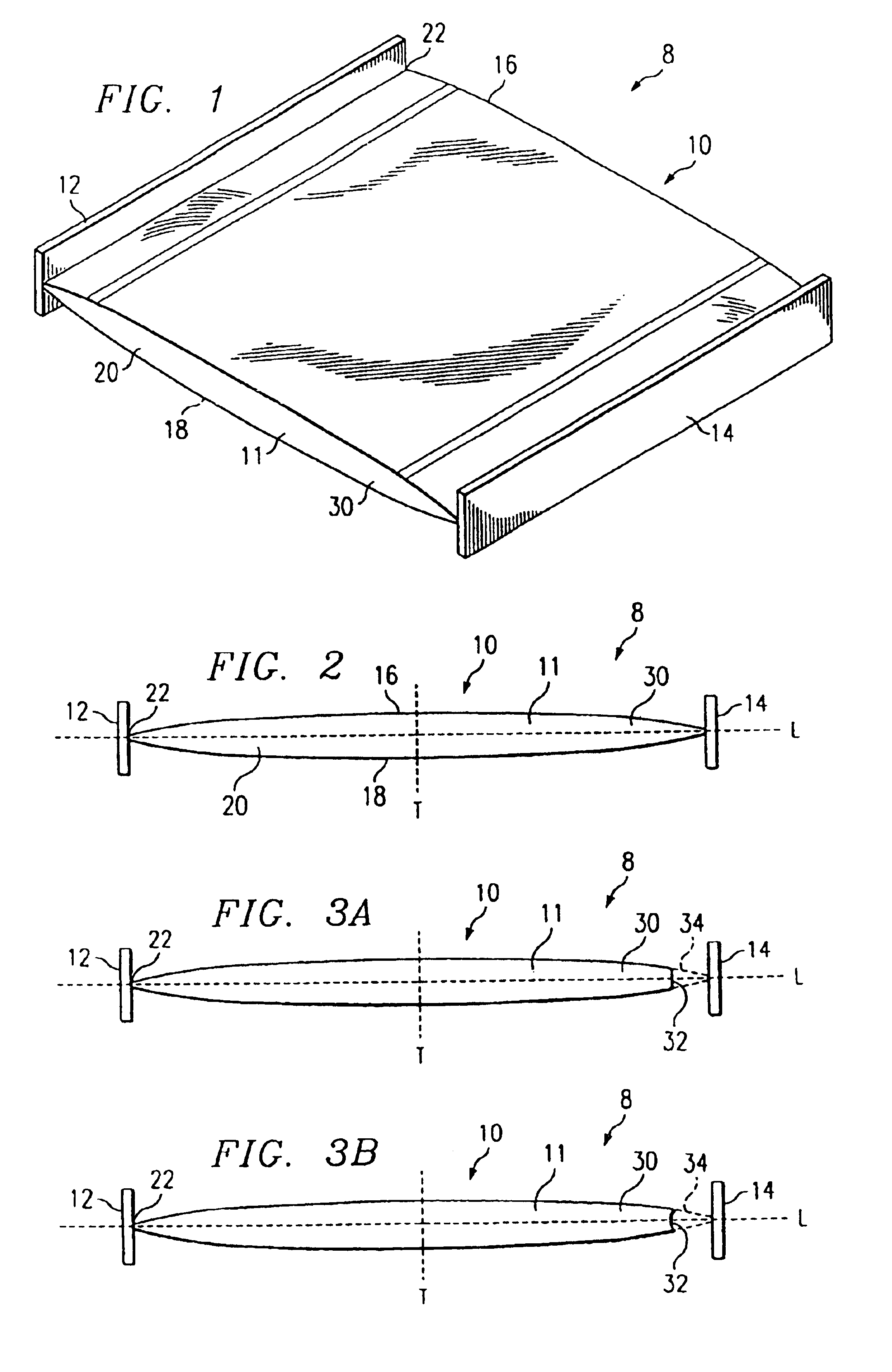
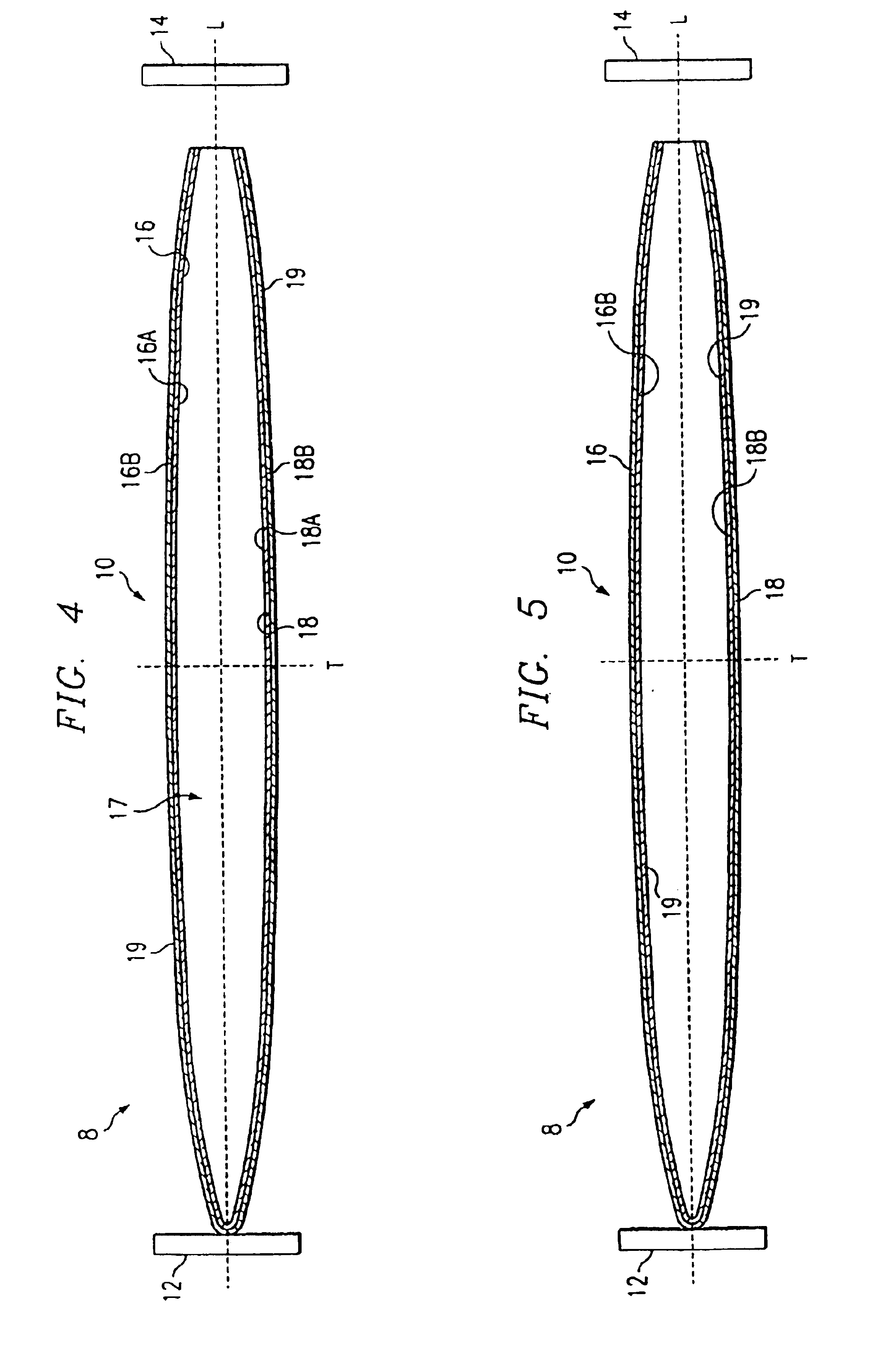
[0021]FIGS. 1 and 2 illustrate an optical transfer system 8 in accordance with one embodiment of the invention. In this embodiment of the present invention, the optical transfer system 8 comprises a light source 12 and a waveguide device 10. The light source 12 and waveguide device 10 of the optical transfer system 8 can be assembled using fixtures and techniques known in the industry. The present invention can be used in a variety of suitable articles and devices desiring the collection and transfer of light, such as a digital film processing system (see FIG. 6), a copier, a scanner, and various medical devices.

[0022]Light source 12 in the optical transfer system 8 is generally positioned relative to the waveguide device 10 so that the transfer or transmission of light to the waveguide device 10 is optimized. In one embodiment, the light source 12 is positioned adjacent one end 22 of the waveguide device 10, and preferably, in an abutting relationship with end 22, as exemplified in...


PUM


Abstract

A waveguide device including a light transmitting body having a first surface, a second surface, and a longitudinal axis where at least one of the first and second surfaces, and preferably both surfaces, are configured to extent in a direction non-parallel to the longitudinal axis. The body of the waveguide can be configured in an elliptical shape along the longitudinal axis, whereby a proximal portion of the waveguide device is symmetrical with a distal portion. The waveguide device being elliptically configured can be combined with a light to form an optical transfer system.

Description

[0001]This is a Divisional application of U.S. application Ser. No. 09 / 730,332 filed Dec. 5, 2000 now U.S. Pat. No. 6,628,884.TECHNICAL FIELD OF THE INVENTION[0002]The present invention relates generally to light transfer devices and systems, and more particularly to a device used with a light transfer system for efficiently transferring light from a light source to an image plane.BACKGROUND OF THE INVENTION[0003]It is common practice to collect light and transmit light or electromagnetic energy from one location to another location in the form of rays or beams. In the past, light, which has been radiated in many directions, has been collected, and then relayed, focused or scanned by mirrors, lenses, and / or prisms. Optical light beams diverge and broaden, but they can be refocused by the use of lenses and mirrors. When using lenses, a typical condenser system (e.g., lens to collect light) projects the source of light onto an image plane. Since the light source is imaged, the light s...

Claims


Application Information

Patent Timeline
Patent Type & Authority Patents(United States)
IPC IPC(8): F21V8/00G02B6/10G02B6/42H04N1/028G02B6/00
CPCG02B6/0046G02B6/10H04N1/02815H04N1/0284G02B6/4298G02B6/0055G02B6/032H04N2201/0408G02B2006/0098
Inventor DUONG, DUNG T.
Owner EASTMAN KODAK CO
Learn More