
Endoscope

a technology of endoscope and endoscope, which is applied in the field of endoscope, can solve problems such as deterioration in workability

Inactive Publication Date: 2006-12-21
OLYMPUS CORP
View PDF3 Cites 1233 Cited by
  • Summary
  • Abstract
  • Description
  • Claims
  • Application Information

AI Technical Summary

Benefits of technology

The present invention is an endoscope that has a slender insertion section with image capturing means at the distal portion, an operating section at the rear end, and a cable section that extends integrally or separately. The cable section has a connector that can be easily detached and mounted onto a light source device and a signal processing device. The operating section has a mounting / detaching portion that allows for the connection of a first unit and a second unit. The technical effects of this invention are that it allows for easy detachment and mounting of the endoscope components, making it convenient for users and facilitating the replacement of components.

Problems solved by technology

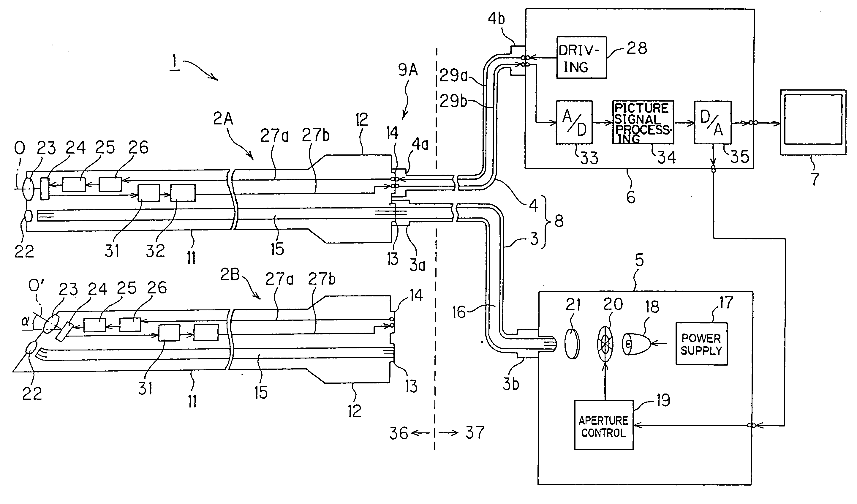
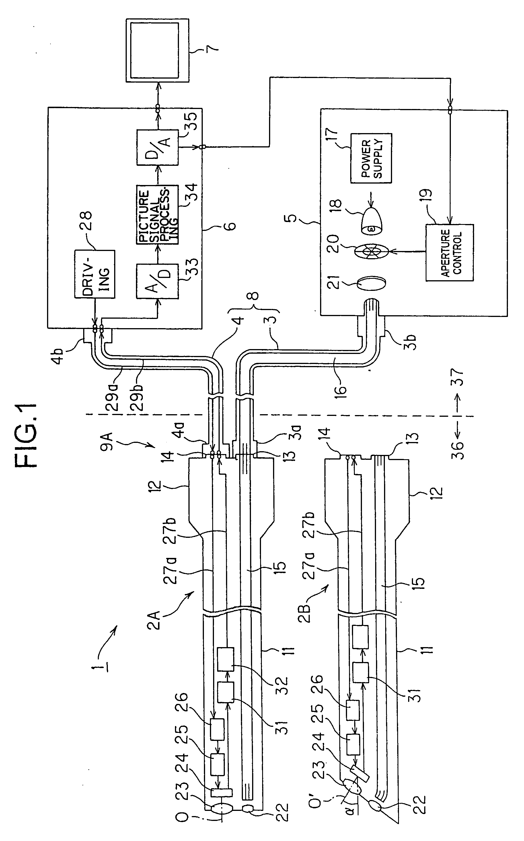
Accordingly, in the event of changing the line of sight between that of a direct viewing type and a perspective type during surgery, a light guide connector at the terminal portion of a light guide cable and a connector for a signal processing device (processor device), which are in unclean areas in general, need to be detached and mounted again, but a surgeon in a clean area cannot perform the process thereof directly, consequently resulting in deterioration in workability thereof.

Method used


Image

  • Endoscope
  • Endoscope
  • Endoscope

Examples


first embodiment

[0052]FIG. 1 illustrates the configuration of a medical endoscope system including a first embodiment of the present invention. As illustrated in FIG. 1, this endoscope system 1 comprises a direct-viewing-type rigid endoscope main body 2A, a perspective-type rigid endoscope main body 2B, a light guide cable section 3 and a signal cable section 4 each of which one end is freely detachably connected to the rigid endoscope main body 2I (I is A or B), a light source device 5 to which the other end of the light guide cable section 3 is freely detachably connected for supplying illumination light, a processor device 6 to which the other end of the signal cable section 4 is freely detachably connected for performing signal processing, and a monitor 7 to which the processor device 6 is freely detachably connected for displaying the corresponding image in response to a picture signal being input.

[0053] Connecting the light guide cable section 3 and the signal cable section 4, which constitu...

second embodiment

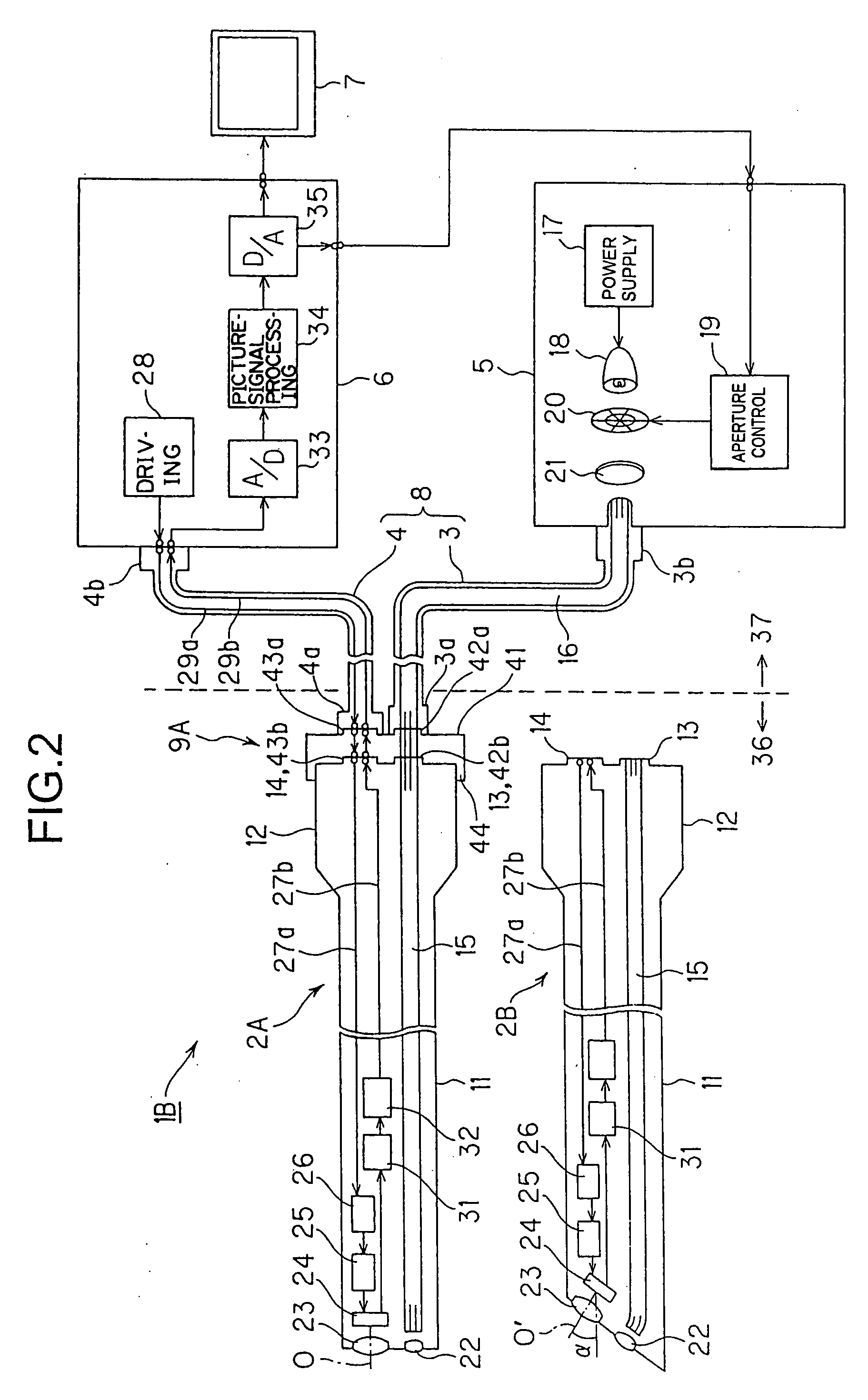
[0080] Next, a second embodiment of the present invention will be described with reference to FIG. 2. FIG. 2 illustrates an endoscope system 1B including the second embodiment.

[0081] This endoscope system 1B enables connection between the rigid endoscope main body 2I, and the light guide cable section 3 and the signal cable section 4 to be performed via a connection adapter 41 in the endoscope system 1 in FIG. 1.

[0082] That is to say, connectors 42a and 43a to be freely detachably connected with the connector receptacles 3a and 4a of the light guide cable section 3 and the signal cable section 4 are provided at one end portion side of the connection adapter 41. Also, connector receptacles 42b and 43b, which can be freely detachably connected to the connectors 13 and 14 in the rigid endoscope main body 2I by one-touch operation, are provided at the other end portion side of the connection adapter 41. The other configurations are the same as those in the first embodiment.

[0083] Thi...

third embodiment

[0087] Next, a third embodiment of the present invention will be described with reference to FIG. 3. The present embodiment employs an integral connector (or integral adapter) 51 wherein the connector receptacles 3a and 4a which are the sides connected to the endoscope main bodies 2A or 2B in the light guide cable section 3 and the signal cable section 4 in the first embodiment. In other words, the present embodiment provides a configuration wherein with the second embodiment in FIG. 2, the connection adapter 41 is integrated with a part of the connector receptacles 3a and 4a sides in the light guide cable section 3 and the signal cable section 4.

[0088] That is to say, the rigid endoscope 9A (or 9B) according to the third embodiment comprises the rigid endoscope main body 2A, and a cable unit 52 wherein the integral connector 51, which can be freely detachably connected to the rigid endoscope main body 2A, is provided.

[0089] With the integral connector 51, a light guide connector ...


PUM


Abstract

An endoscope includes a slender insertion section of which the distal portion incorporates an image capturing device, and the back end of this insertion section is provided with an operating section to be gripped. A cable section is provided wherein a light guide cable for transmitting illumination light, and a signal cable connected to the image capturing device are integrally or separately extended from the operating section, and the connector of the edge portion of the cable section is freely detachably mounted to each of a light source device and a signal processing device. A mounting / detaching portion for freely detachably connecting a first unit serving as an insertion section side and a second unit serving as a cable section side is provided around between the distal end of the operating section and the proximal end thereof.

Description

CROSS REFERENCE TO RELATED APPLICATION [0001] This application is a continuation application of PCT / JP2005 / 003325 filed on Feb. 28, 2005 and claims the benefit of Japanese Applications No. 2004-057914 filed in Japan on Mar. 2, 2004, and No. 2004-334882 filed in Japan on Nov. 18, 2004, the entire contents of each of which are incorporated herein by their reference.BACKGROUND OF THE INVENTION [0002] 1. Field of the Invention [0003] The present invention relates to an endoscope for subjecting a body cavity or the like to endoscopy. [0004] 2. Description of the Related Art [0005] In recent years, endoscopes capable of subjecting the inside of a test object to inspection in the medical-application and industrial-application fields have been widely employed. [0006] As for a conventional example, there is a rigid endoscope including a hard insertion section, which incorporates an image capturing device. With this rigid endoscope, a light guide cable and a scope cable are integrated within ...

Claims


Application Information

Patent Timeline
Patent Type & Authority Applications(United States)
IPC IPC(8): A61B1/00G02B23/24A61B1/06
CPCA61B1/00105A61B1/00114A61B1/00117G02B23/2484A61B1/00181A61B1/05G02B23/2469A61B1/00142A61B1/00165
Inventor TSUJI, KIYOSHIHAGIHARA, MASAHIRO
Owner OLYMPUS CORP
Learn More