
Apparatus and method for isolating optics from thermal expansion

a technology of thermal expansion and optics, applied in the field of imagers, can solve the problems of not reducing convergence and focus drift, and achieve the effects of reducing thermal flexing effects on the frame, and reducing convergence and focus dri

Inactive Publication Date: 2005-05-03
THOMSON LICENSING SA
View PDF5 Cites 0 Cited by
  • Summary
  • Abstract
  • Description
  • Claims
  • Application Information

AI Technical Summary

Benefits of technology

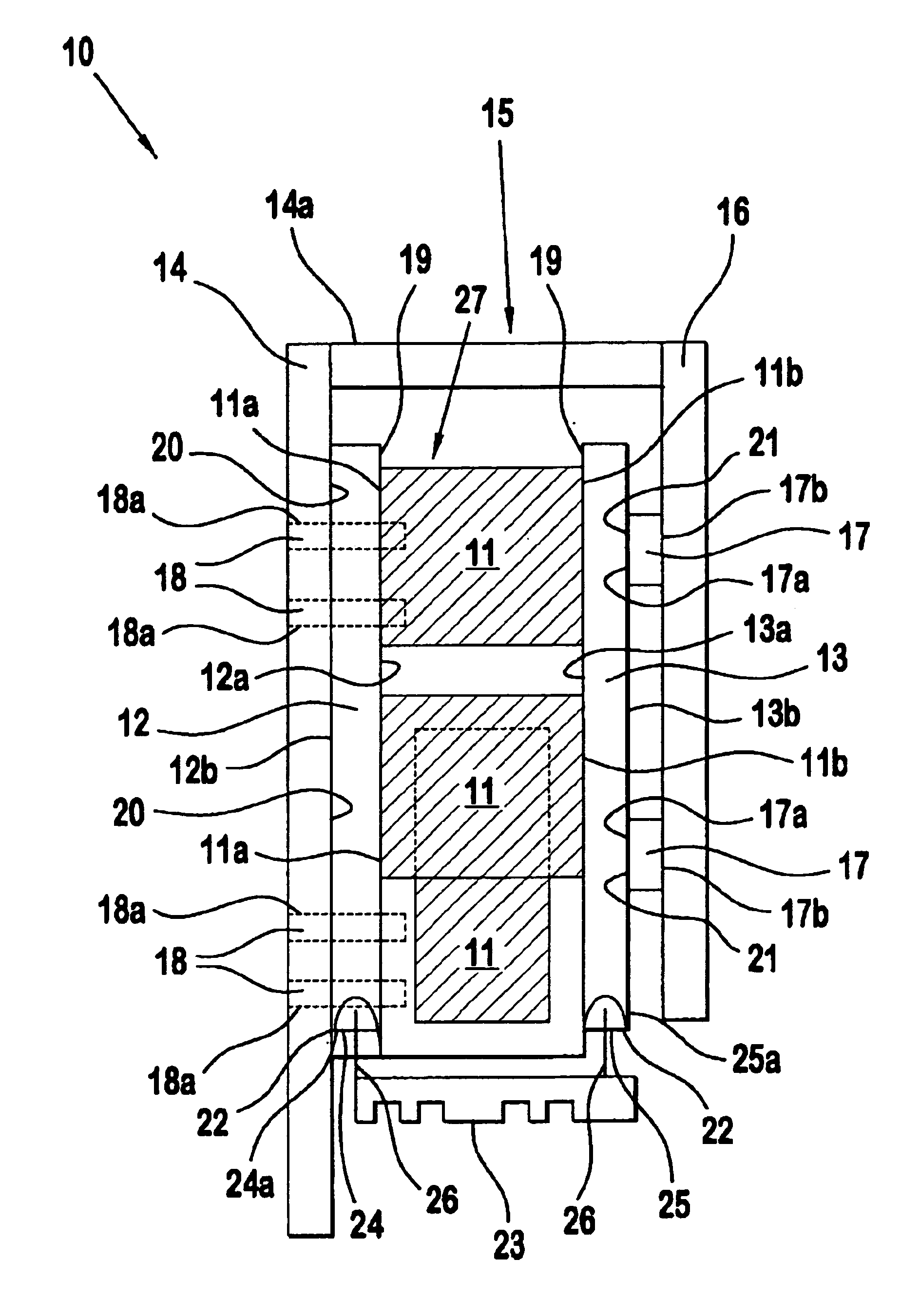
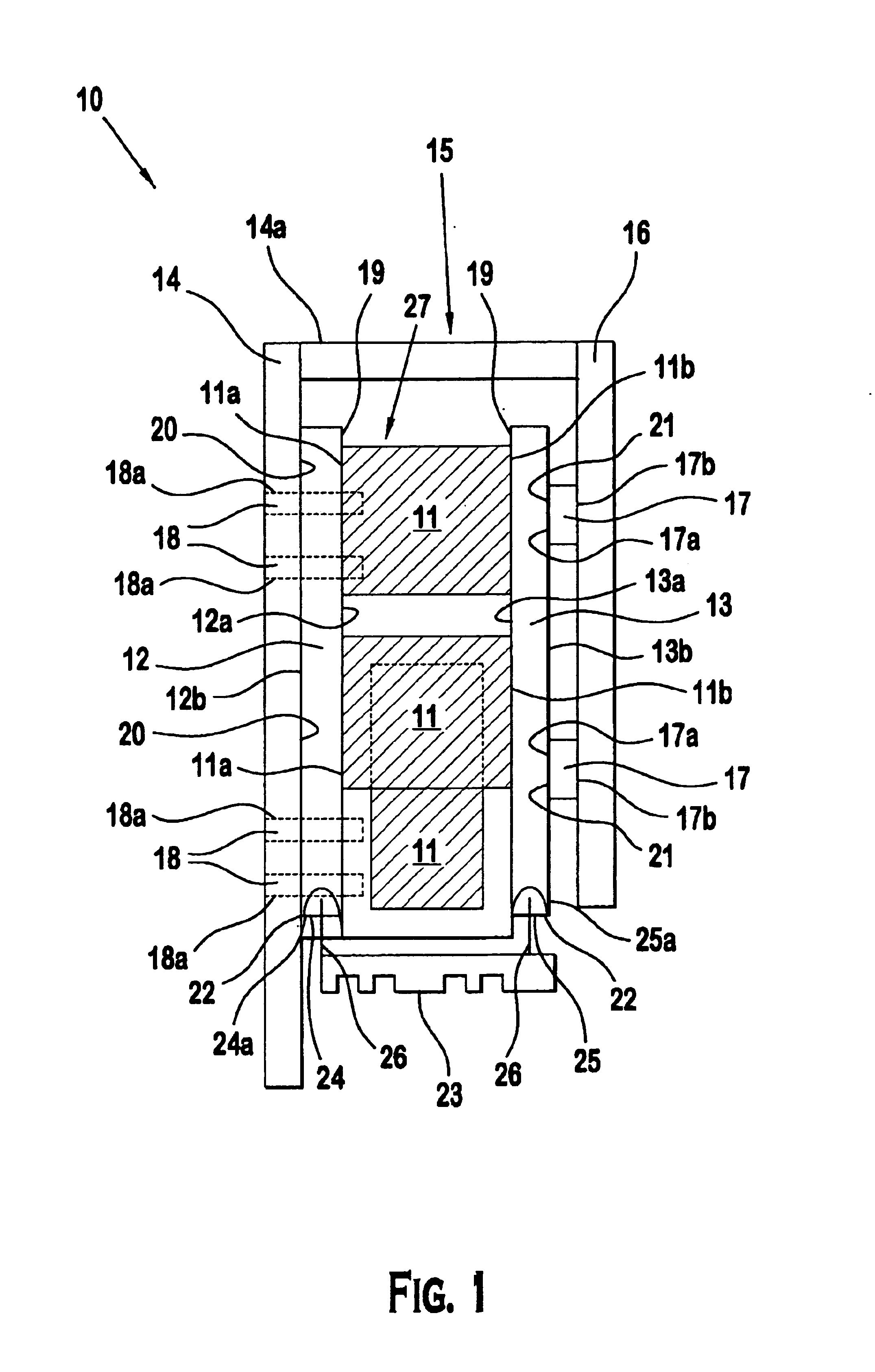
[0008]An apparatus that reduces convergence and focus drift in imager prism assemblies includes at least one prism assembly having a first side and a second side. The first side communicates with a first isolator inner surface and a second side communicates with a second isolator inner surface. The first and second isolator reduce the convergence and focus drift of the prism assembly. An outer surface of the first isolator communicates with a first position of a frame for mounting the prism assembly. An outer surface of the second isolator communicates with a top side of an damping member for reducing the thermal flexing effects on the frame. A bottom side of the damping member communicates with a second position of the frame for mounting the prism assembly. There is at least one guide pin at each prism assembly located through the first isolator and the first position for initial alignment of the prism assembly.
[0009]A first adhesive secures the first side to the first isolator inner surface and the first adhesive secures the second side to the second isolator inner surface. A second adhesive secures the first isolator outer surface to the first position and the second adhesive secures the second isolator outer surface with the top side. A third adhesive secures the bottom side to the second position and a bottom end of the first and second isolator communicates with a plate to further reduce the convergence and focus drift of the prism assembly.

Problems solved by technology

However, the display device does not reduce the convergence and focus drift of its prism assembly due to thermal fluxing.

Method used


Image

  • Apparatus and method for isolating optics from thermal expansion
  • Apparatus and method for isolating optics from thermal expansion
  • Apparatus and method for isolating optics from thermal expansion

Examples


Embodiment Construction

[0014]While the present invention is described below with reference to an imager for a LCoS light engine, a practitioner in the art will recognize the principles of the present invention are applicable elsewhere.

[0015]FIG. 1 illustrates apparatus 10 as an embodiment of the invention. Apparatus 10 reduces the convergence drift and focus drift in imager prism assemblies resulting from thermal flexing of the device. When the metal frame 15, where the imager prism assemblies 11 are mounted, expands or contracts due to thermal changes in the metal frame, the prism assemblies 11 become misaligned. The metal frame includes the first member 14, the second member 16, a tie member 14a which secures the first member 14 to the second member 16 and a plate 23. Typically, frame 15 is constructed of aluminum which has a high coefficient of expansion and thermally flexes in temperature cycling. The expansion and / or contraction of the frame 15 pushes the sensitive alignment of the prisms out of the ...


PUM


Abstract

An apparatus that reduces convergence and focus drift in imager prism assemblies includes at least one assembly having a first side and a second side. The first side communicates with a first isolator inner surface and a second side communicates with a second isolator inner surface. An outer surface of the first isolator communicates with a first member of a frame. An outer surface of the second isolator communicates with a top side of a damping member. A bottom side of the damping member communicates with a second member of the frame. There is at least one guide pin located through the first isolator and the first member.A first adhesive secures the first side to the first isolator inner surface and the first adhesive secures the second side to the second isolator inner surface. A second adhesive secures the first isolator outer surface to the first member and the second adhesive secures the second isolator outer surface with the top side. A third adhesive secures the bottom side to the second member and a bottom end of the first and second isolator communicates with a plate.

Description

FIELD OF THE INVENTION[0001]This invention relates to imagers in liquid crystal on silicon (LCOS) light engines and more particularly, to an application that isolates prism assemblies from thermal expansion reducing convergence and focus drift.BACKGROUND OF THE INVENTION[0002]Liquid crystal displays (LCDs) are becoming increasingly prevalent in high-density projection display devices. These conventional high density projection color display devices include a light source which emits white light. Dichroic mirrors separate the white light into its corresponding red, green and blue (RGB) bands of light. These color bands of light are then directed toward a corresponding liquid crystal valve which either permits or prevents the light transmission. The RGB bands of light which are permitted to be transmitted through the light valves are then combined by a prism assembly. A projection lens then magnifies and projects the image onto a projection screen.[0003]A conventional liquid crystal p...

Claims


Application Information

Patent Timeline
Patent Type & Authority Patents(United States)
IPC IPC(8): H04N9/31
CPCH04N9/3141H04N9/3197H04N9/317H04N5/74G03B21/00G02B7/18H04N9/31
Inventor ARCHER, JR., CARL DOUGLAS
Owner THOMSON LICENSING SA
Learn More