Vascular embolic filter exchange devices and methods of use thereof

Inactive Publication Date: 2005-05-03
INCEPT LLC
View PDF239 Cites 85 Cited by
  • Summary
  • Abstract
  • Description
  • Claims
  • Application Information

AI Technical Summary

Benefits of technology

[0008]The present invention pertains to embolic protection systems deployed in a body vessel or cavity for the collection of loosened and / or dislodged debris, such as embolic material dislodged during, or thrombi formed as a result of, an interventional procedure. The present invention is particularly helpful to protect the vasculature of a patient from dislodged emboli during interventional procedures such as angioplasty, atherectomy, thrombectomy, embolectomy, intravascular diagnostic and stent placement procedures by enabling rapid exchange of embolic filters during the course of the interventional procedure.
[0009]Vascular embolic filter systems, as well as methods for using the same, are provided. In one particular embodiment, the subject invention includes a system comprised of an embolic filter assembly and a multiple lumen delivery and retrieval sheath, where the embolic filter assembly includes a guide wire with an embolic filter operatively coupled to the guide wire for capturing emboli created during interventional procedures within a target vessel. Features of the subject systems provide for the rapid exchange and deployment of embolic filters in a patient's vasculature. Rapid exchange of embolic filters during the course of a procedure decreases overall procedure times and minimizes the risks associated with occluded embolic filters.
[0010]Specifically, the rapid exchange of embolic filters is accomplished by sequentially retrieving an occluded filter and deploying a second, unused or unoccluded filter through a single delivery and retrieval sheath having at least two lumens, without having to remove the occluded filter and / or the sheath prior to delivering and deploying the second filter.
[0011]As such, a first embolic filter is deployed to a target site distal to a stenosis such that the first deployed embolic filter creates an opening or mouth through which emboli and debris can flow. Once a first embolic filter is deployed, an interventional device can be advanced to the site of the stenosis and the interventional procedure may commence. Once filled with emboli and debris, the interventional device is removed from the vessel. The multiple lumen delivery and retrieval sheath of the present invention is then advanced over the guide wire in order to retrieve the first embolic filter and to deliver and deploy a second embolic filter. The guide wire with the first embolic filter attached is pulled or retracted into the first lumen of the sheath, or alternatively the sheath is advanced over the guide wire and attached embolic filter, causing the filter opening or mouth to close or collapse. Such withdrawal prevents emboli collected during the procedure from escaping into the patient's blood. Once the first embolic filter is effectively withdrawn into a lumen of the delivery and retrieval sheath so as to prevent the escape of collected emboli, a second embolic filter can be deployed to the target site through a second lumen of the delivery and retrieval sheath. Again, when filled with emboli and debris, the second deployed embolic filter can also be retrieved by withdrawing it at least partially into a second lumen of the delivery and retrieval sheath in order to sufficiently close or collapse the filter mouth to prevent the escape of emboli from the embolic filter. Additional filters can also be rapidly advanced, deployed and retrieved as described above, in certain embodiments through additional lumens within the multiple lumen delivery and retrieval sheath.
[0012]In another embodiment of the present invention, an interventional device such as an angioplasty catheter, embolectomy device, atherectomy device or the like is advanced to the procedure site through one of the lumens of the multiple lumen delivery and retrieval sheath of the present invention. In certain embodiments, embolic filter exchange and the interventional procedure can occur without the need to remove the sheath from the vasculature between exchanges, thus further reducing procedure times.

Problems solved by technology

Vascular procedures to treat occlusive vascular diseases, such as angioplasty, atherectomy and stent placement, often cause blood clots to form and / or material to dislodge from inside the vessel walls and enter the bloodstream.
However, there are significant disadvantages associated with this approach, including increased procedural complexity, the need for additional components and the inability to completely aspirate emboli entrapped in the filter pores.

Method used


Image

  • Vascular embolic filter exchange devices and methods of use thereof
  • Vascular embolic filter exchange devices and methods of use thereof
  • Vascular embolic filter exchange devices and methods of use thereof

Examples


Embodiment Construction

Rapid Exchange Embolic Filter System

Embolic Filter Assembly

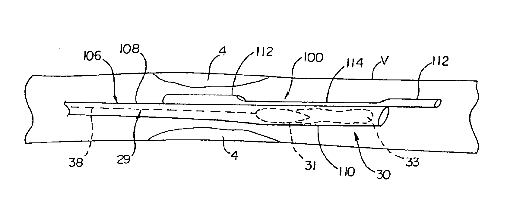
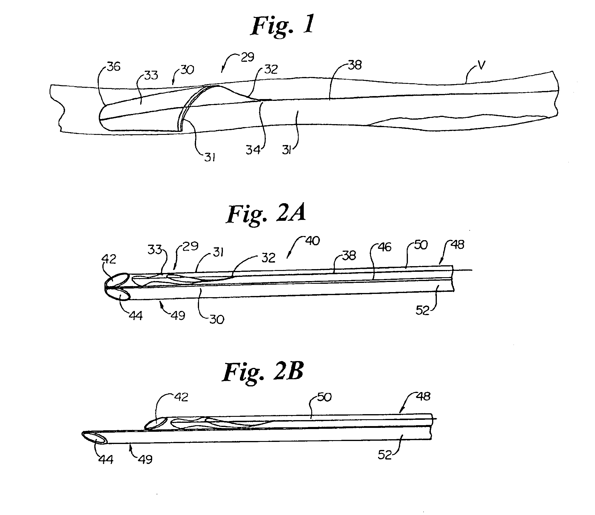
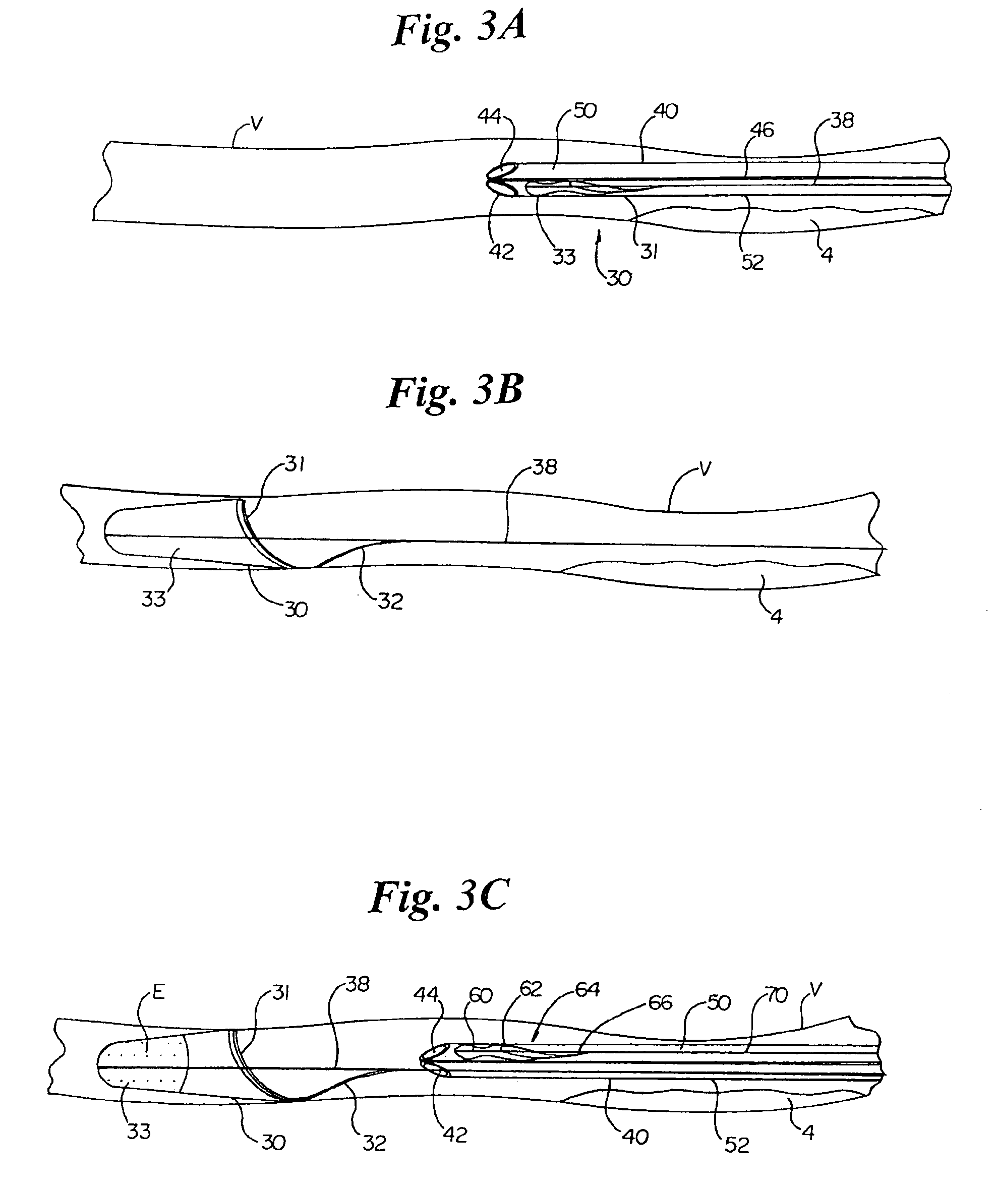
[0036]An embolic filter assembly of the present invention is comprised of an embolic filter operatively coupled to a guide wire. A number of embolic filters are known for providing distal protection against embolization in conjunction with a transluminal diagnostic or therapeutic procedure, such as angioplasty or embolectomy. These embolic filters are deployed distal to a vascular lesion, such as a stenosis, prior to undertaking the diagnostic or therapeutic procedure, and are designed to collect emboli liberated during the procedure to prevent them from entering the blood stream. Generally, embolic filters suitable for use with the present invention are characterized by having a blood permeable sac and a support hoop which forms an opening into the sac; however, other types of filters are also useable with the present invention.

[0037]Referring now to FIG. 1, a schematic of an embolic filter assembly suitable for use with th...


PUM


Abstract

Vascular embolic filtering systems, as well as methods for using the same, are provided. In general, the subject invention includes a system comprised of an embolic filter assembly and a multiple lumen delivery and retrieval sheath, where the embolic filter assembly includes a guide wire with an embolic filter operatively coupled to the distal end of the guide wire for capturing emboli created during interventional procedures within a target vessel. Features of the subject invention provide for the rapid exchange and deployment of embolic filters in a patient's vasculature.

Description

FIELD OF THE INVENTION[0001]The present invention relates to systems and methods for filtering and removing matter from within the vasculature. More particularly, the invention is directed to the intravascular exchange of intravascular devices useful for capturing emboli generated during interventional procedures, and for thrombectomy and embolectomy procedures.BACKGROUND OF THE INVENTION[0002]Vascular procedures to treat occlusive vascular diseases, such as angioplasty, atherectomy and stent placement, often cause blood clots to form and / or material to dislodge from inside the vessel walls and enter the bloodstream. The dislodged material (e.g., plaque), known as emboli, may be large enough to occlude smaller downstream vessels, potentially blocking blood flow to tissue. Additionally, the blood clots, known as thrombi, may be large enough or grow over time to form a blockage at the interventional site or at another downstream location should the thrombus become released into the bl...

Claims


Application Information

Patent Timeline
IPC IPC(8): A61F2/01
CPCA61F2/013A61F2230/0008A61F2002/018A61F2230/008A61F2/011
Inventor SALAHIEH, AMRDEMOND, JACKSONKROLIK, JEFF
Owner INCEPT LLC
Why Eureka
Try Eureka