
Movable guide for transmission device

a technology of moving contact and transmission device, which is applied in the direction of belt/chain/gearing, mechanical equipment, belts/chains/gearings, etc., can solve the problems of not being able to improve the bending rigidity, toughness and strength of the entire guide, and not being able to increase the largest allowable load in a conventional movable. , to achieve the effect of preventing the transmission medium from running, preventing the vibration of the transmission medium, and reducing the vibration of th

Inactive Publication Date: 2005-04-26
TSUBAKIMOTO CHAIN CO
View PDF7 Cites 29 Cited by
  • Summary
  • Abstract
  • Description
  • Claims
  • Application Information

AI Technical Summary

Benefits of technology

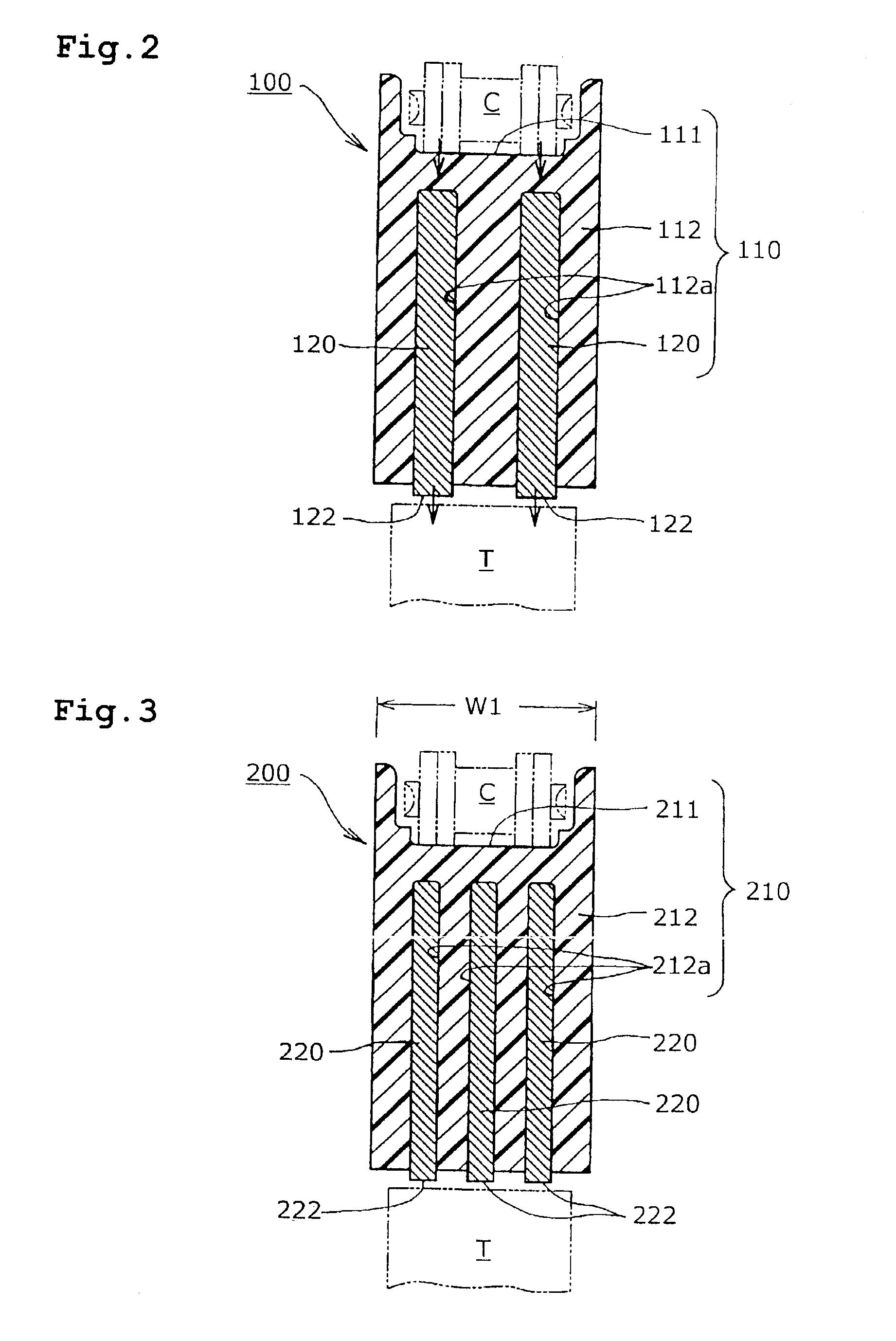
[0017]The use of plural reinforcing plates in the guide suppresses widthwise vibration of the flexible transmission medium, and also prevents running of the transmission medium off the guide in the widthwise direction.
[0018]When a tensioner-contacting portion connects the plates to one another and extends across at least a portion of the rearwardly facing surface of the plate-receiving portion, the guide becomes particularly stable and strongly resistant to the effects of widthwise forces. The tensioner-contacting portion which connects the plates not only ensures a stable guide position, but also avoids guide torsion and falling down of the guide, and ensures a stable travel of the flexible transmission medium.
[0019]The provision of aligned mounting holes in the plate-receiving portion of the guide body and in the reinforcing plates prevents the plates from becoming dislodged from the guide body and suppresses vibrational contact between the guide body and the reinforcing plates, which is otherwise produced as a result of movement of a chain, belt or the like along the guide.

Problems solved by technology

However, the practical limit to the thickness of the reinforcing plate is about 4.5 mm.
Consequently, it is not possible to improve the bending rigidity, toughness, and strength of the entire guide beyond what is afforded by a plate having a thickness of about 4.5 mm, and there is no room for increasing the largest allowable load in a conventional movable guide.
10(b), are liable to occur, so that traveling movement of the chain becomes unstable.
As a result, excessive pressure is applied to portion F2.
Moreover, the chain tends to move widthwise off the guide, which causes instability in the movement of the chain.
Thus, a reinforcing plate produced by pressing a rolled steel sheet cannot be used satisfactorily under the heavy load conditions encountered in an engine, such as a diesel engine, in which two timing chains are arranged in parallel to each other.
However, the space available in the engine limits the height H, and a reinforcing plate 520 having increased height cannot be used in engines designed in accordance with the recent trend toward increased load and greater compactness.

Method used


Image

  • Movable guide for transmission device
  • Movable guide for transmission device
  • Movable guide for transmission device

Examples


Embodiment Construction

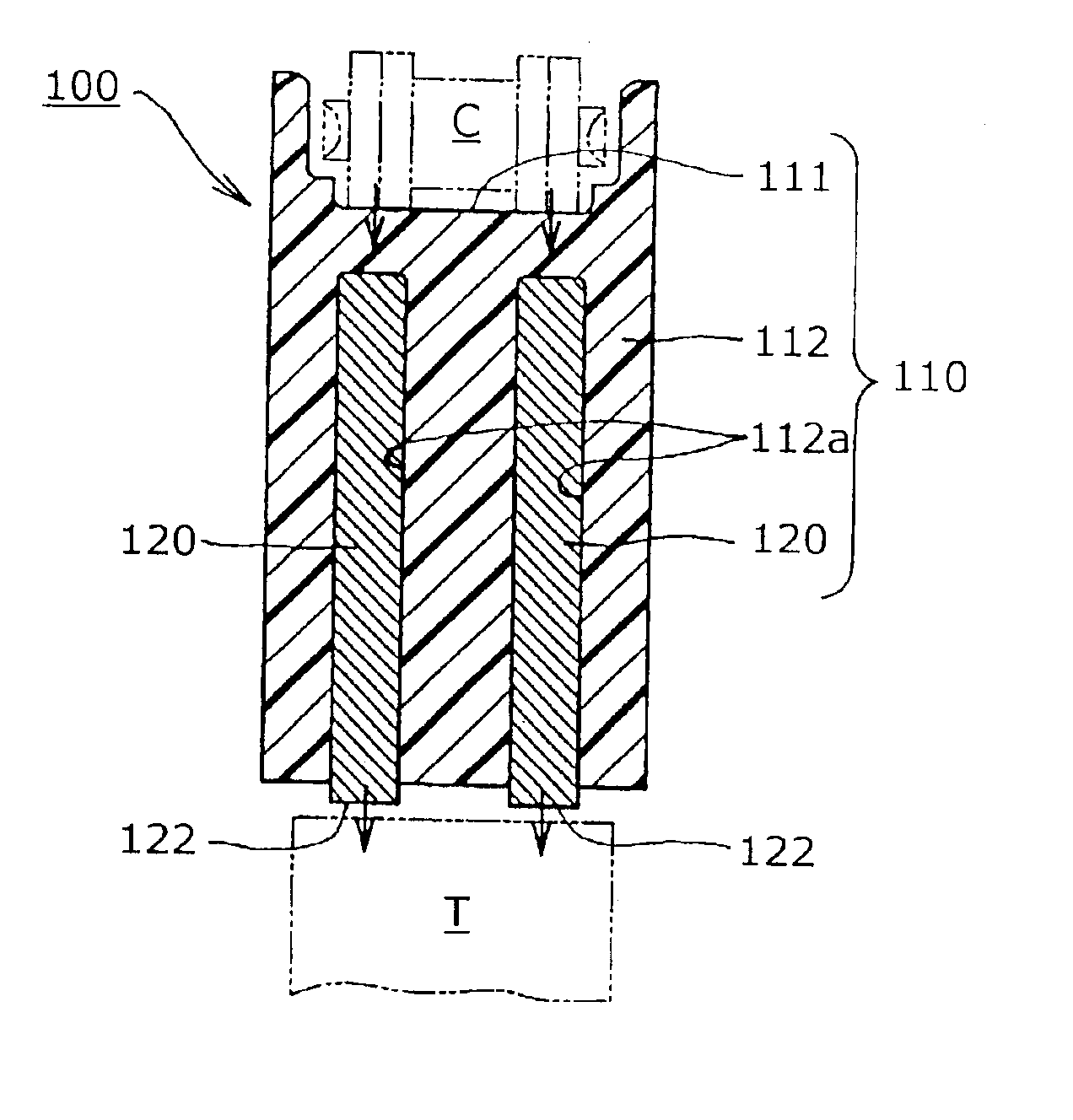
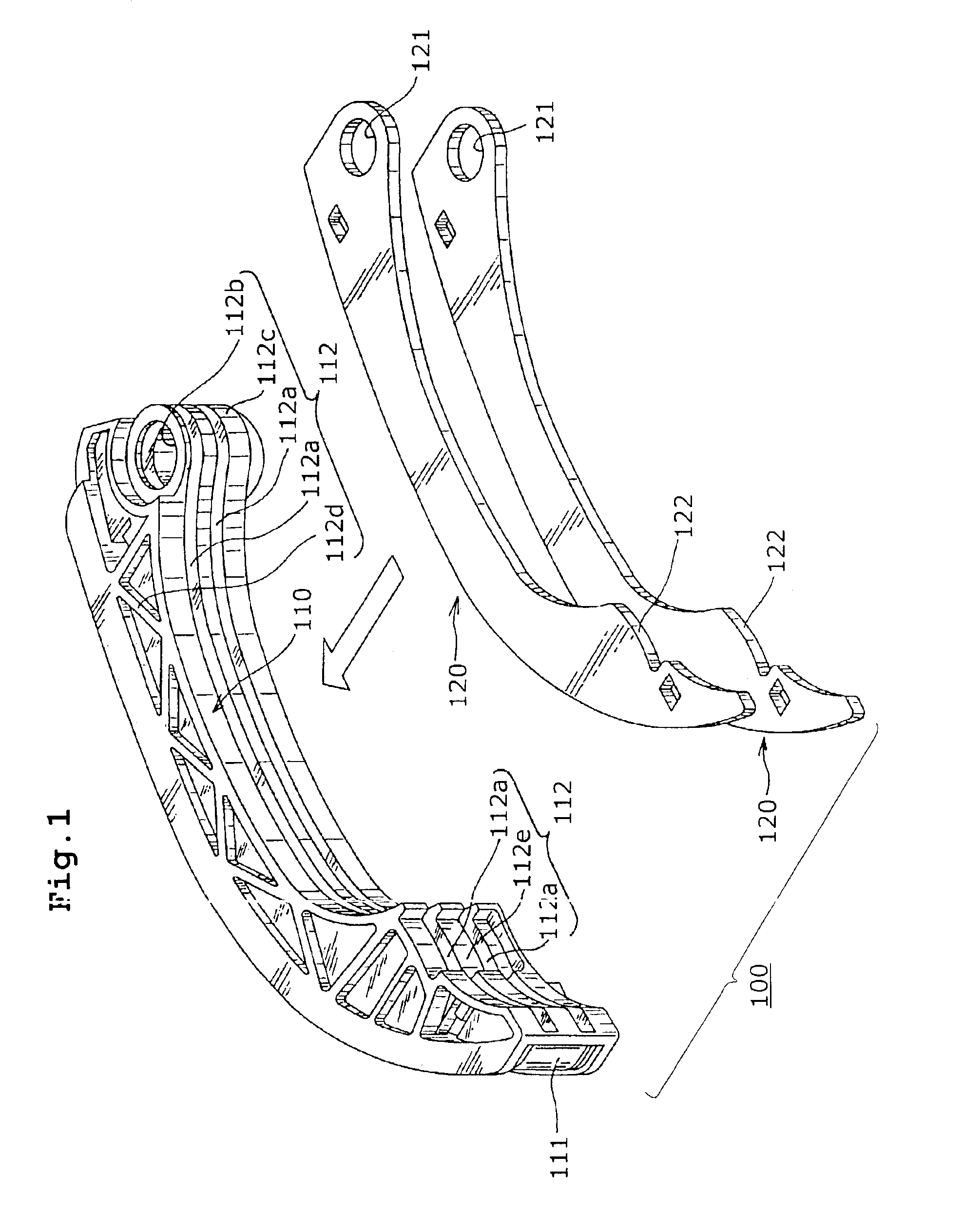
[0032]The movable guide 100, shown in FIG. 1, is designed to be pivotally attached to an engine on a mounting shaft in order serve as a tensioner lever to control tension in a traveling chain. The guide 100 comprises an integrally molded, synthetic resin guide body 110, and two metallic reinforcing plates 120 punched from a steel sheet. The guide is produced by inserting the two reinforcing plates 120 into slots 112a in the synthetic resin guide body 110 in the direction illustrated by the arrow.

[0033]The guide body 110 comprises a shoe 111 having transmission medium-contacting surface on which a chain, belt or the like slides, and plate-receiving portions 112 provided on the back sides of the shoe 111 and extending along the longitudinal direction of the guide. Further, the plate-receiving slots 112a have their openings facing away from the shoe, in a direction opposite to the direction in which the transmission medium-contacting surface faces. The slots extend parallel to each oth...


PUM


Abstract

In a movable guide for transmission device in which a guide body is formed from a synthetic resin and comprises a chain-contacting shoe and a plate-receiving portion formed as a unit with the shoe on the back side thereof, the plate-receiving portion has plural, longitudinally extending slots, each receiving a reinforcing plate. The plural reinforcing plates improve the bending rigidity, toughness, strength and wear properties of the guide, prevent falling down of the guide and guide torsion, ensure stable travel of the chain, and prevent running of the chain off the guide in a widthwise direction. Improved compactness of the guide and of the overall mechanism, is made possible by the use of plural plates. The plates can be connected to one another by a tensioner-contacting portion, formed as a unit with the plates.

Description

FIELD OF THE INVENTION[0001]This invention relates to a sliding contact guide for a power transmission utilizing an endless, circulating, flexible power transmission medium. It relates, for example, to a guide in a chain drive transmission, in which a chain transmits power from a driving sprocket to a driven sprocket, or to a guide in a belt drive transmission, in which a belt transmits power from a driving pulley to a driven pulley.BACKGROUND OF THE INVENTION[0002]In general, as shown in FIG. 6, a chain or belt transmission device for valve timing in an internal combustion engine, or for transmitting rotational power in another drive mechanism, includes a chain or belt C, which transmits power from a driving sprocket or pulley S1 to one or more driven sprockets or pulleys S2. The transmission includes a pivotally mounted, movable sliding contact guide Ga, which cooperates with a tensioner T, and a fixed sliding contact guide Gb. The movable guide and the fixed guide are attached to...

Claims


Application Information

Patent Timeline
IPC IPC(8): F16H7/18F16H7/00F16H7/08
CPCF16H7/18F16H2007/0872
Inventor KONNO, MASAHIKOSATOH, TOSHIFUMI
Owner TSUBAKIMOTO CHAIN CO
Learn More