
Method and system for recovering carbon dioxide

a carbon dioxide and carbon dioxide technology, applied in the field of carbon dioxide recovery, can solve the problems of amine absorption process and the inability to reduce the output of power plants, and achieve the effect of high thermal efficiency

Active Publication Date: 2005-04-26
MITSUBISHI HEAVY IND ENG LTD
View PDF10 Cites 95 Cited by
  • Summary
  • Abstract
  • Description
  • Claims
  • Application Information

AI Technical Summary

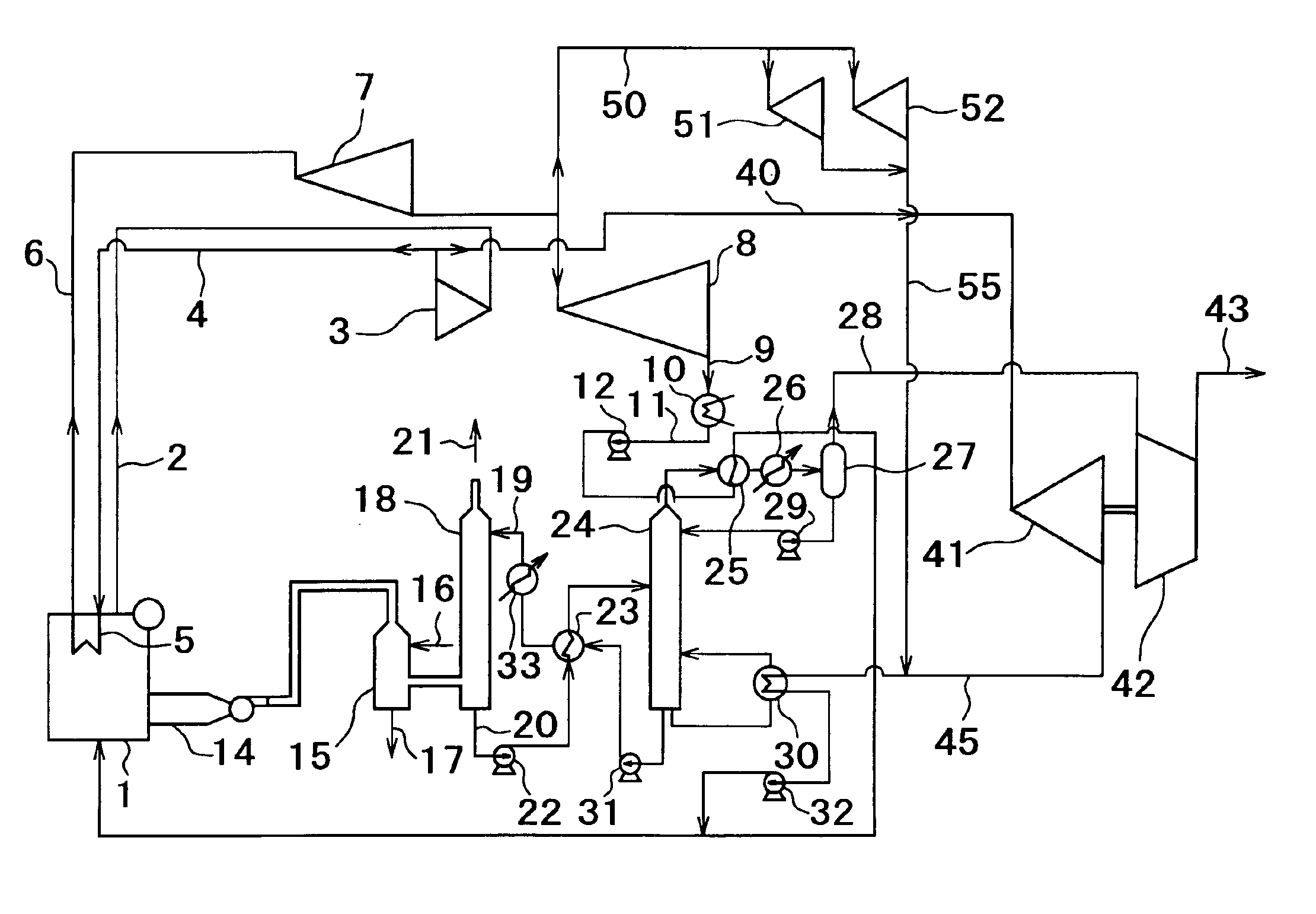
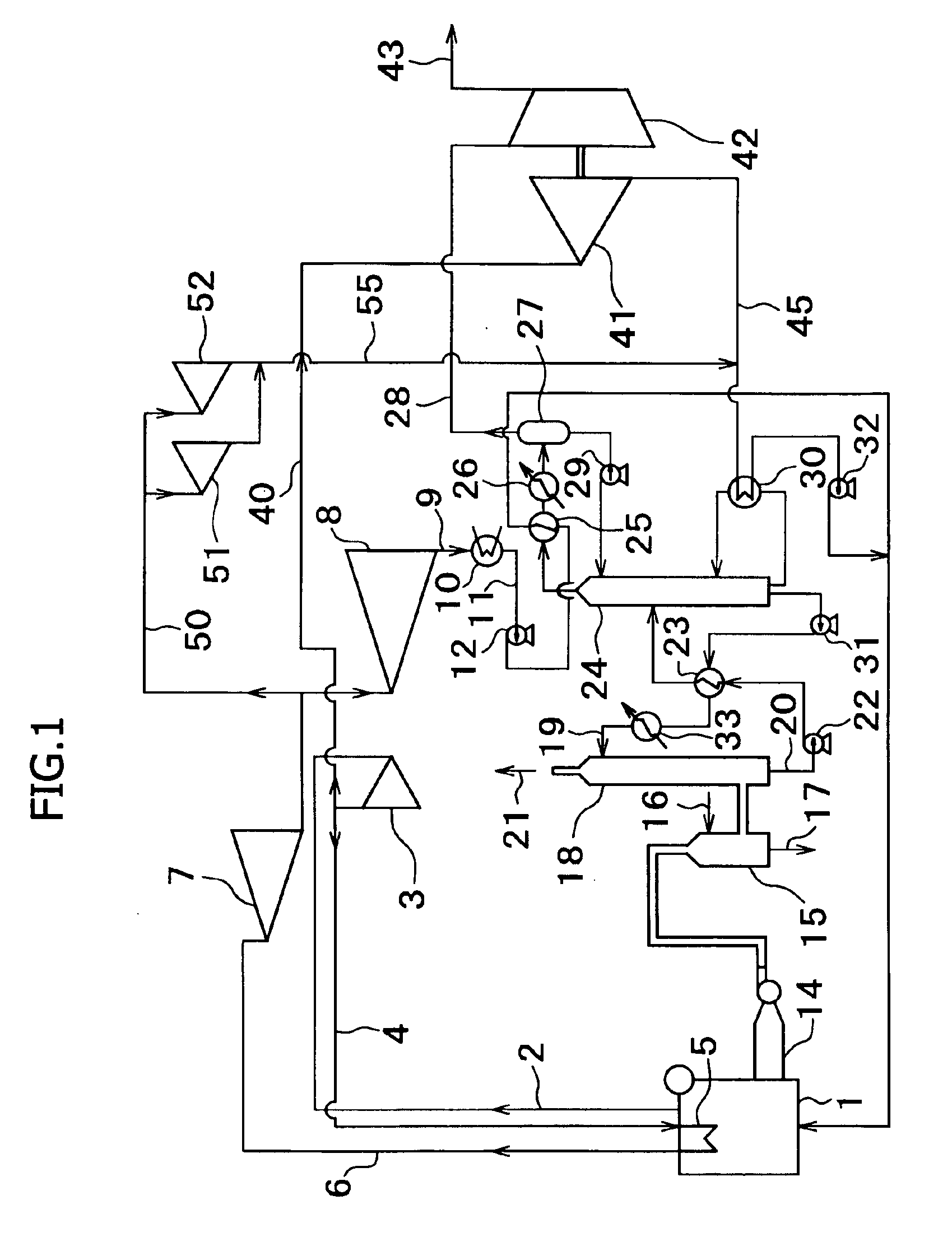
Benefits of technology

[0003]The present invention has been made to solve the above problems, and accordingly an object thereof is to provide a method for recovering carbon dioxide, in which thermal energy for regenerating a carbon dioxide absorbing solution and power for compressing the recovered carbon dioxide are supplied, and high thermal efficiency is achieved, and a system therefor.
[0009]As described above, according to the present invention, there can be provided a method for recovering carbon dioxide, in which thermal energy for regenerating a carbon dioxide absorbing solution and power for compressing the recovered carbon dioxide are supplied, and high thermal efficiency is achieved, and a system therefor.

Problems solved by technology

However, the amine absorption process has a problem of requiring thermal energy from a large amount of low-pressure steam (for example, about 0.3 MPa) to regenerate an absorbing solution having absorbed CO2.
However, in order to inject CO2 under pressure, it is necessary to compress CO2 to a high pressure (for example, about 140 kg / cm2G), and when a power source for such compression is secured, the output of power plant inevitably decreases significantly.

Method used


Image

  • Method and system for recovering carbon dioxide
  • Method and system for recovering carbon dioxide

Examples


Embodiment Construction

[0012]In FIG. 1, only principal equipment is shown, and auxiliary equipment is omitted. If necessary, tanks, valves, pumps, heat exchangers, and the like are additionally provided. Although low pressure, intermediate pressure, and high pressure turbines are usually provided in pairs, these turbines are represented by a single symbol, and a generator attached to these turbines is also omitted.

[0013]As shown in FIG. 1, the system for recovering carbon dioxide (CO2) in accordance with the present invention includes a boiler 1 having a reheater 5, a high pressure turbine driven by steam of the boiler 1, an intermediate pressure turbine 7 driven by exhaust steam of the high pressure turbine 3, which is heated by the reheater 5, and a low pressure turbine 8 driven by exhaust steam of the intermediate pressure turbine 7. The exhaust side of the low pressure turbine 8 is connected to the boiler 1 via a condenser 10 for condensing exhaust gas and an overhead condenser 25 for carrying out hea...


PUM


Abstract

To provide a method for recovering carbon dioxide, in which thermal energy for regenerating a CO2 absorbing solution and power for compressing the recovered CO2 are supplied, and high thermal efficiency is achieved, and a system therefor. A system for recovering carbon dioxide including a high pressure turbine 3, an intermediate pressure turbine 7, and a low pressure turbine 8; a boiler 1 for generating steam for driving the turbines; an absorption tower 18 filled with a CO2 absorbing solution for absorbing and removing CO2 from combustion exhaust gas of the boiler; a regeneration tower 24 for regenerating the absorbing solution having absorbed CO2; a compressor 42 for compressing the removed CO2; a turbine 41 for a compressor, which is driven by some of the exhaust steam of the high pressure turbine; turbines 51 and 52 for auxiliary machinery, which are driven by some of the exhaust steam of the intermediate pressure turbine; and supply pipes 45 and 55 for supplying exhaust steam of the compressor turbine and the auxiliary machinery turbines to a reboiler 30 of the regeneration tower as a heating source.

Description

BACKGROUND OF THE INVENTION[0001]The present invention relates to a method for recovering carbon dioxide, in which in a thermal electric power plant, carbon dioxide contained in combustion exhaust gas of boiler is removed and recovered, and a system therefor.[0002]In power generating equipment in a thermal electric power plant using large quantities of fossil fuel, as a method for removing and recovering carbon dioxide (CO2), which is one cause for global warming, an amine absorption process has been used (for example, see Japanese Patent Provisional Publication No. 8-257355). However, the amine absorption process has a problem of requiring thermal energy from a large amount of low-pressure steam (for example, about 0.3 MPa) to regenerate an absorbing solution having absorbed CO2. On the other hand, there have been developed a technique for fixing recovered CO2 under pressure in an underground aquifer, a technique for injecting CO2 under pressure into an oil field, a technique for i...

Claims


Application Information

Patent Timeline
IPC IPC(8): B01D53/14B01D53/62B01J19/00C01B32/50
CPCB01D53/1475Y02C10/06Y02C10/04Y02C20/40
Inventor IIJIMA, MASAKISUGITA, SATORUKOBAYASHI, YOSHINORIKUROISHI, TOSHIRO
Owner MITSUBISHI HEAVY IND ENG LTD
Learn More