
Radio communication system

a radio communication and system technology, applied in the field of radio communication systems, can solve the problems of insufficient level or quality of mobile terminal ps transmission inability to increase the transmission power and the upper limit of mobile terminal ps transmission power, so as to reduce the disconnection ratio of calls, suppress the increase of interference, and increase the propagation loss of a radio line

Inactive Publication Date: 2005-04-12
NEC CORP
View PDF9 Cites 11 Cited by
  • Summary
  • Abstract
  • Description
  • Claims
  • Application Information

AI Technical Summary

Benefits of technology

The present invention is a radio communication system that reduces disconnection of calls and interference between mobile terminals during data communication. The system includes a base station and a mobile terminal. The base station transmits a data signal and power control signals to the mobile terminal through a forward channel. The mobile terminal transmits data signals to the base station through a reverse channel. The mobile terminal controls the transmission power based on the power control signals. The transmission control unit monitors the transmission power and determines when it exceeds a predetermined maximum value. The transmission control unit also has a counter and a timer to determine the number of power control signals and the time for detecting the maximum transmission power. The technical effect of this invention is to improve the reliability and stability of data communication.

Problems solved by technology

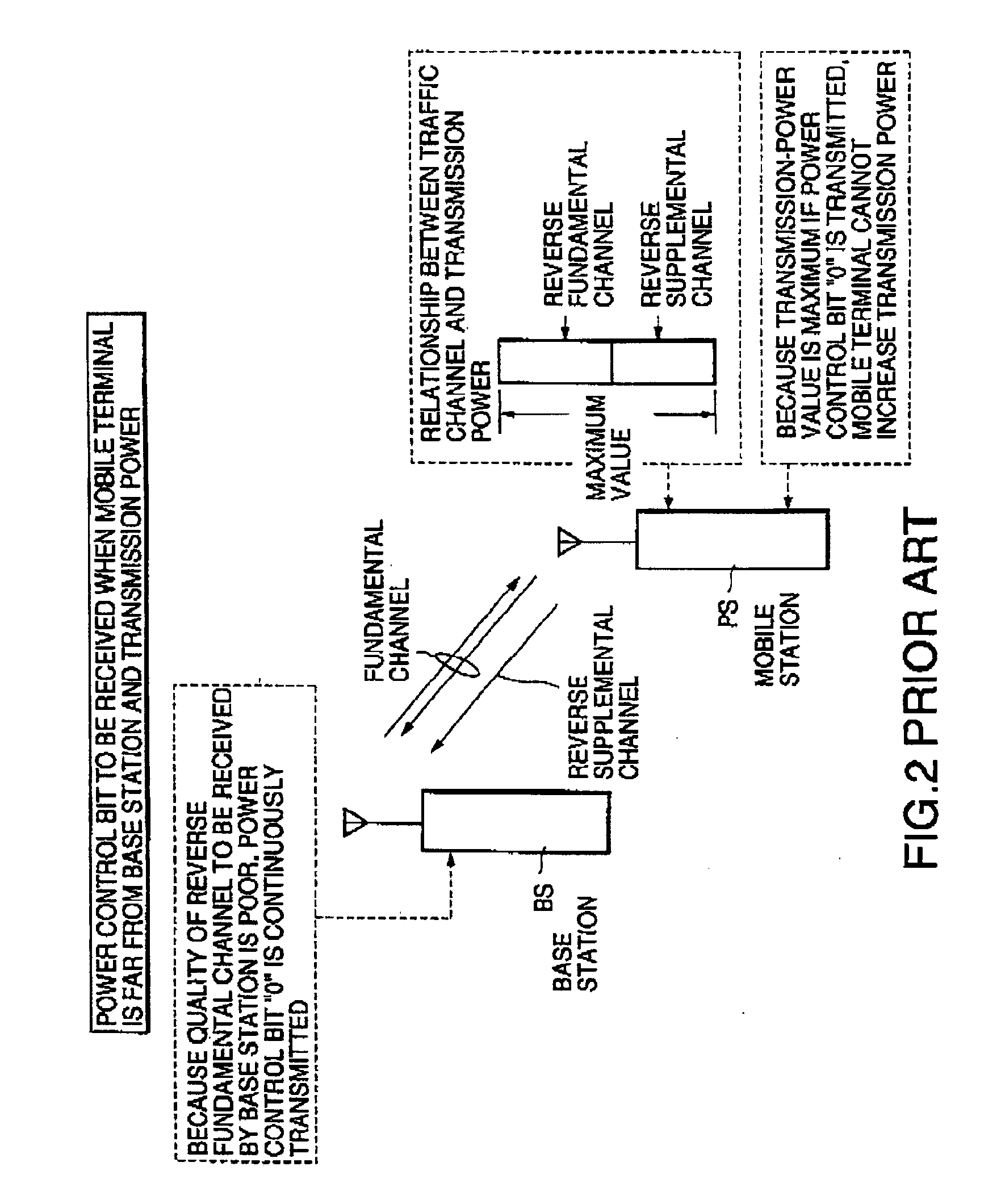
If the mobile terminal PS is located far from the base station and the propagation loss of the radio line increases, the base station BS cannot receive the signal from the mobile terminal PS at the sufficient level or quality.
However, the transmission power of the mobile terminal PS has the upper limit and the transmission power of the mobile terminal PS cannot be increased though the base station instructs the increase in transmission power, as shown in FIG.

Method used


Image

  • Radio communication system
  • Radio communication system
  • Radio communication system

Examples


first embodiment

the present invention will be described with reference to the drawings hereinafter. FIG. 3 is a block diagram of one structure of a mobile terminal constructing a radio communication system of the present invention. The present radio communication system shows an example of the IS-95B specified by a TIA / EIA. The IS-95B system allocates two reverse communication channels (that is, one fundamental channel and one supplemental channel) to one mobile terminal thereby executing fast data communication.

As shown in FIG. 3, the mobile terminal comprises a receiving unit 1 and a transmitting unit 2. The receiving unit 1 has a receiver 10, a demodulating unit 11, a reverse-diffusion unit 12, and a power control bit reading unit 13. The transmitting unit 2 has a transmission data control unit 21 including a counter 20A, a switch 22, diffusion units 23 and 24, an adding unit 25, a modulating unit 26, a transmitter 27, and a transmission power control unit 28.

A description is given of the functi...


PUM


Abstract

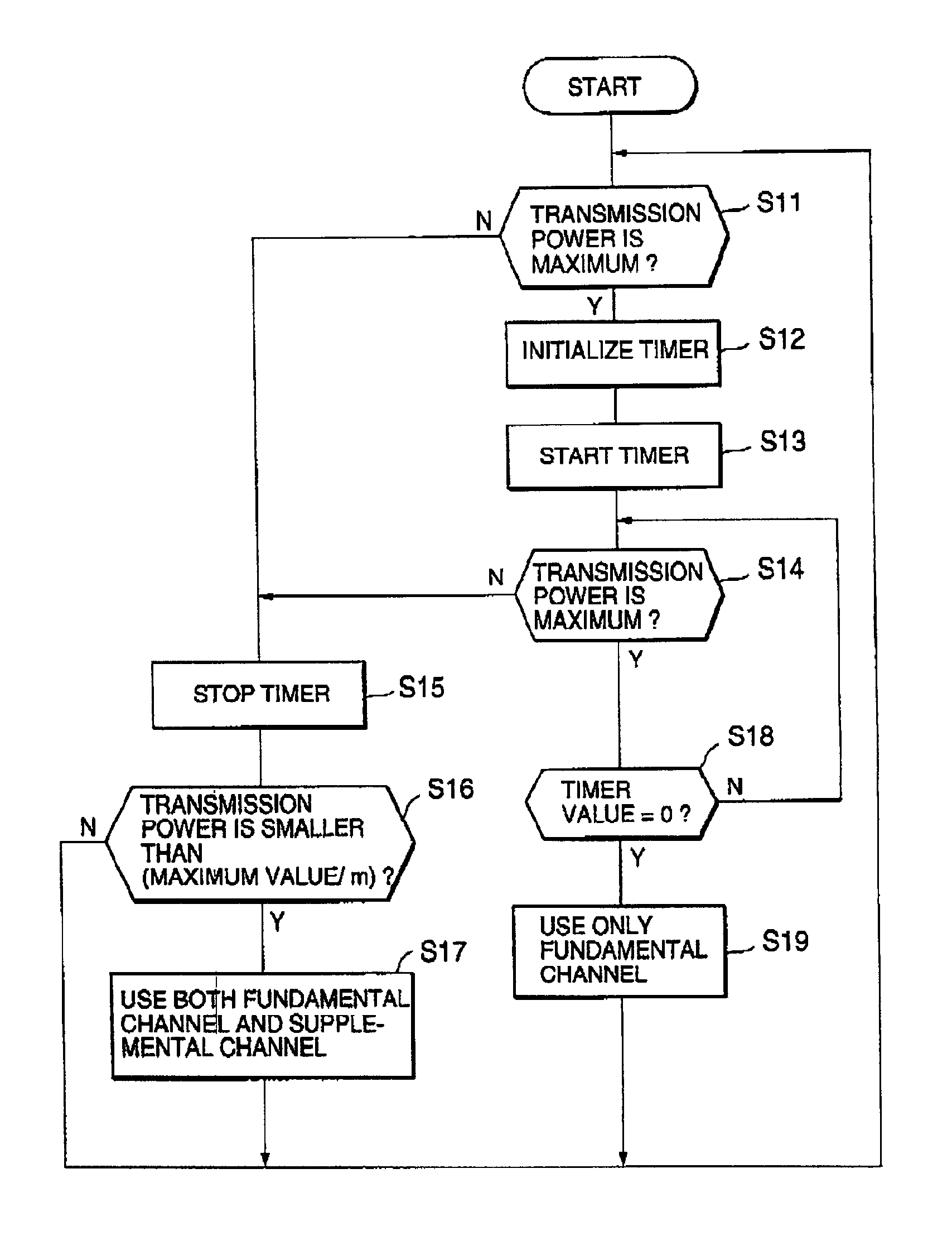
The disconnection ratio of calls of a mobile terminal is reduced when the mobile terminal during communication is located far from a base station and the propagation loss of a radio line increases. In the mobile terminal, when a transmission-power value from a transmission power control unit becomes maximum, a transmission data control unit inputs power control bits “0” and “1” read by a power control bit reading unit and a counter counts the power control bit “0”. If a counted value of the counter exceeds a threshold, the transmission data control unit stops transmission of data through a reverse supplemental channel and switches data transmission to data transmission only through a reverse fundamental channel.

Description

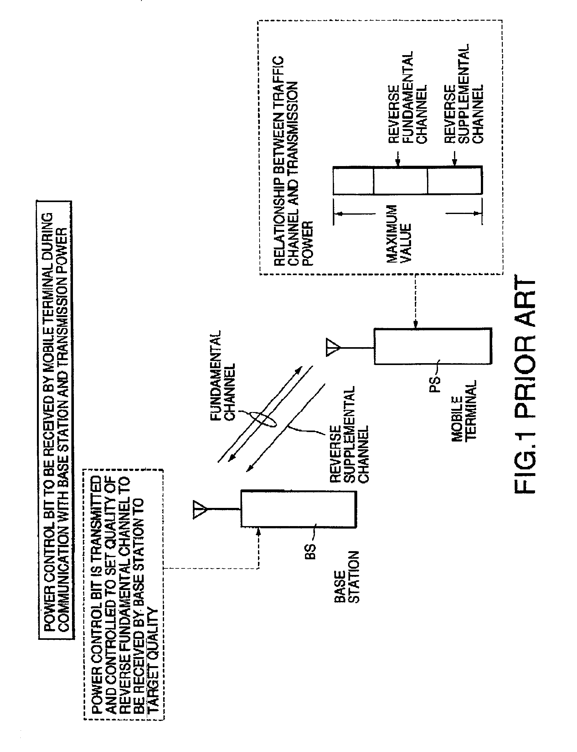
BACKGROUND OF THE INVENTIONThe present invention relates to a radio communication system for radio communication which comprises a base station and a mobile terminal, and is based on a COMA system.An IS-95A system and an IS-95B system are well-known as such a radio communication system. In the IS-95A system, a radio line which a mobile terminal uses for communication is called a traffic channel. In the CDMA method, necessary qualifies of communication through communication channels must be at the lowest level so as to assure a line capacity. For this purpose, a fast power control is requested for, in particular, a reverse line. In the IS-95A system, in order to assure the line capacity, a power control signal “power control bit” is inserted to a forward traffic channel to receive signals from all mobile terminals at a base station with the same quality, thereby controlling transmission powers of the mobile terminals.If the signal received by one base station has an insufficient-qual...

Claims


Application Information

Patent Timeline
Patent Type & Authority Patents(United States)
IPC IPC(8): H04B7/005H04B7/26H04W52/36
CPCH04W52/367H04W52/36
Inventor KOSUGI, JUNICHI
Owner NEC CORP
Learn More