
Dispersion shifted fiber having low dispersion slope

a fiber and dispersion slope technology, applied in the field of dispersion shifted fibers with low dispersion slope, can solve the problems of preventing good dwdm performance, obstructing higher bit rate transmission, and promoting poor dwdm performance, so as to reduce non-linearities, reduce the effect of non-linearity, and high bend resistan

Inactive Publication Date: 2005-04-12
STERLITE TECHNOLOGIES
View PDF10 Cites 34 Cited by
  • Summary
  • Abstract
  • Description
  • Claims
  • Application Information

AI Technical Summary

Benefits of technology

Yet another object of the present invention is to make a complete disclosure of two fibers, which not only have high level of bend resistance but also have minimized non-linearities with optimum chromatic dispersion.
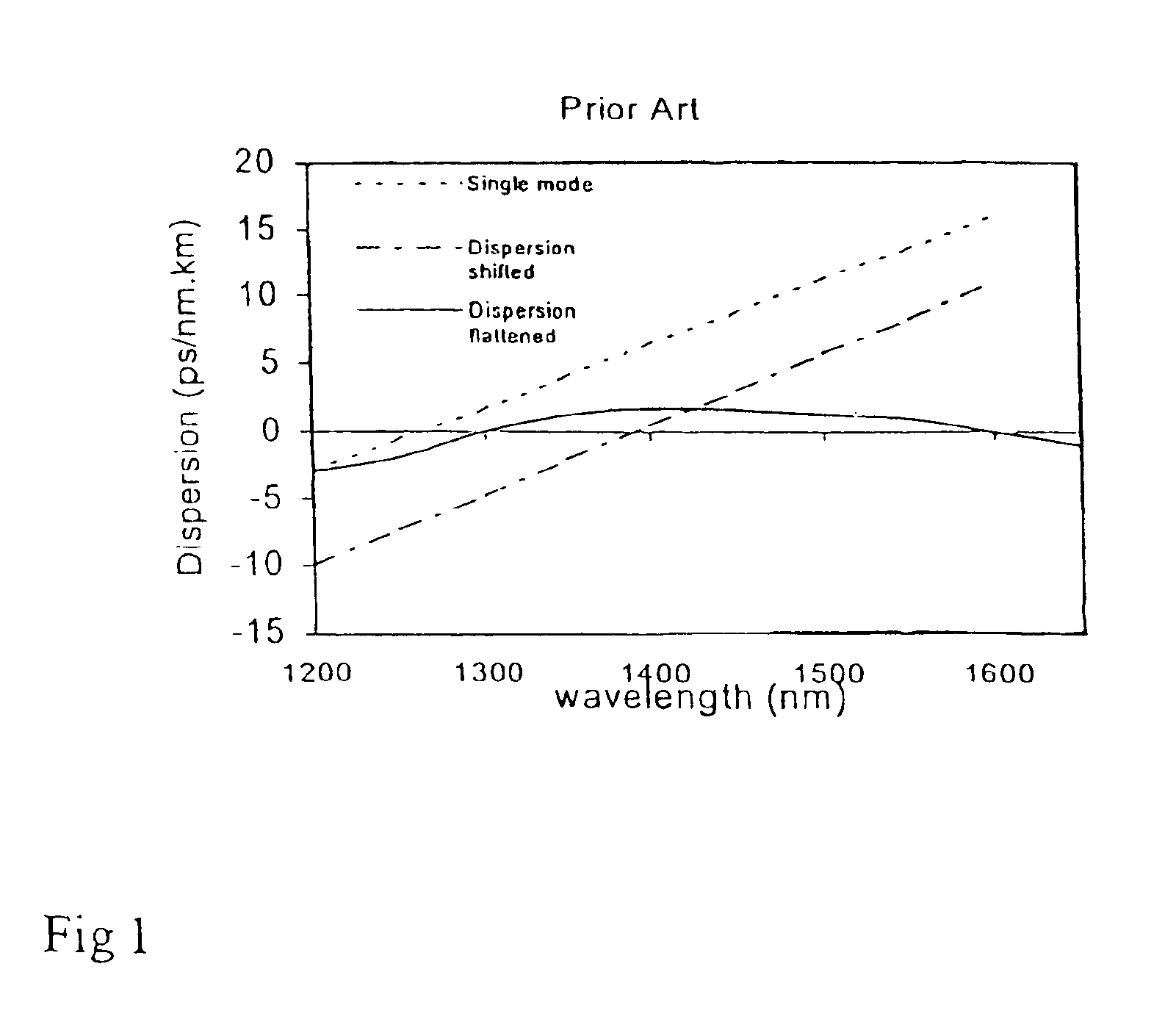
In accordance with theoretical analysis carried out by the inventors, it appears that the main drawbacks and limitations of the prior art can be overcome by a fiber, which has chromatic dispersion between about 2.6 to 6.0 ps / nm.km and about 3.9 to 8.6 ps / nm.km over the operating wavelength 1530 to 1565 nm (C-band) and of 1565 to 1625 nm (L-band) respectively and maximum dispersion slope less than about 0.05 ps / nm2.km over the said wavelength regions. Therefore, in the present invention an attempt has been made to develop a fiber having such a refractive index profile and configuration which is not only easy to be achieved but also easy to be fabricated, wherein said fiber will have chromatic dispersion and dispersion slope characteristics in or closer to said ranges or values.

Problems solved by technology

The major disadvantage of the single mode fibers with high dispersion at 1550 nm was that, it obstructed higher bit rate transmission.
However, the dispersion shifted fibers used for long distance systems in the prior art have higher dispersion which promotes poor DWDM performance.
This result is strong four wave mixing, which prevents good DWDM performance.
The fibers as known in the prior art either have low non-linearity but high bend loss or have low bend loss but less effective area or may have higher non-linearity and higher bend loss or may have non-uniform chromatic dispersion over the third and fourth window or high dispersion slope, that is the fibre will not have optimum characteristic properties and will sacrifice one of the property for achieving another property.

Method used


Image

  • Dispersion shifted fiber having low dispersion slope
  • Dispersion shifted fiber having low dispersion slope
  • Dispersion shifted fiber having low dispersion slope

Examples


Embodiment Construction

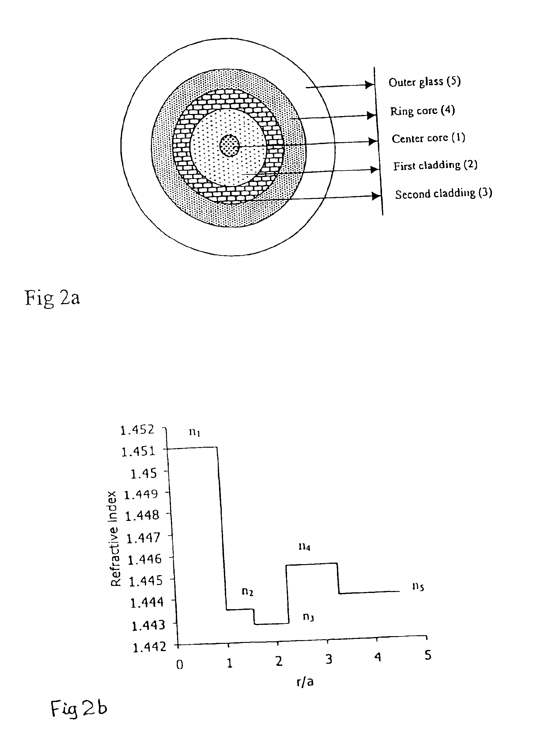
In accordance with the present invention a disclosed optical fiber, shown in FIG. 2a, comprises of a centre core 1, two claddings 2 and 3, a ring core 4 and the outer glass region 5, wherein first cladding 2 is provided onto the outer periphery of the centre core 1, second cladding 3 is provided onto outer periphery of the first cladding 2 and the ring core 4 is provided onto outer periphery of the second cladding 3, and the outer glass region 5 surrounds the ring core 4 [FIG. 2a].

According to this invention the centre core 1 and ring core 4 of the presently disclosed optical fiber have higher refractive indices, and the claddings 2 and 3 have lower refractive indices than that of the outer glass region 5 [FIG. 2b]. The refractive index of the centre core 1, first cladding 2, second cladding 3, ring core 4 and outer glass region 5 are identified by symbols n1, n2, n3, n4 and n5 respectively and in accordance with the present invention, these refractive indices are so selected that ...


PUM


Abstract

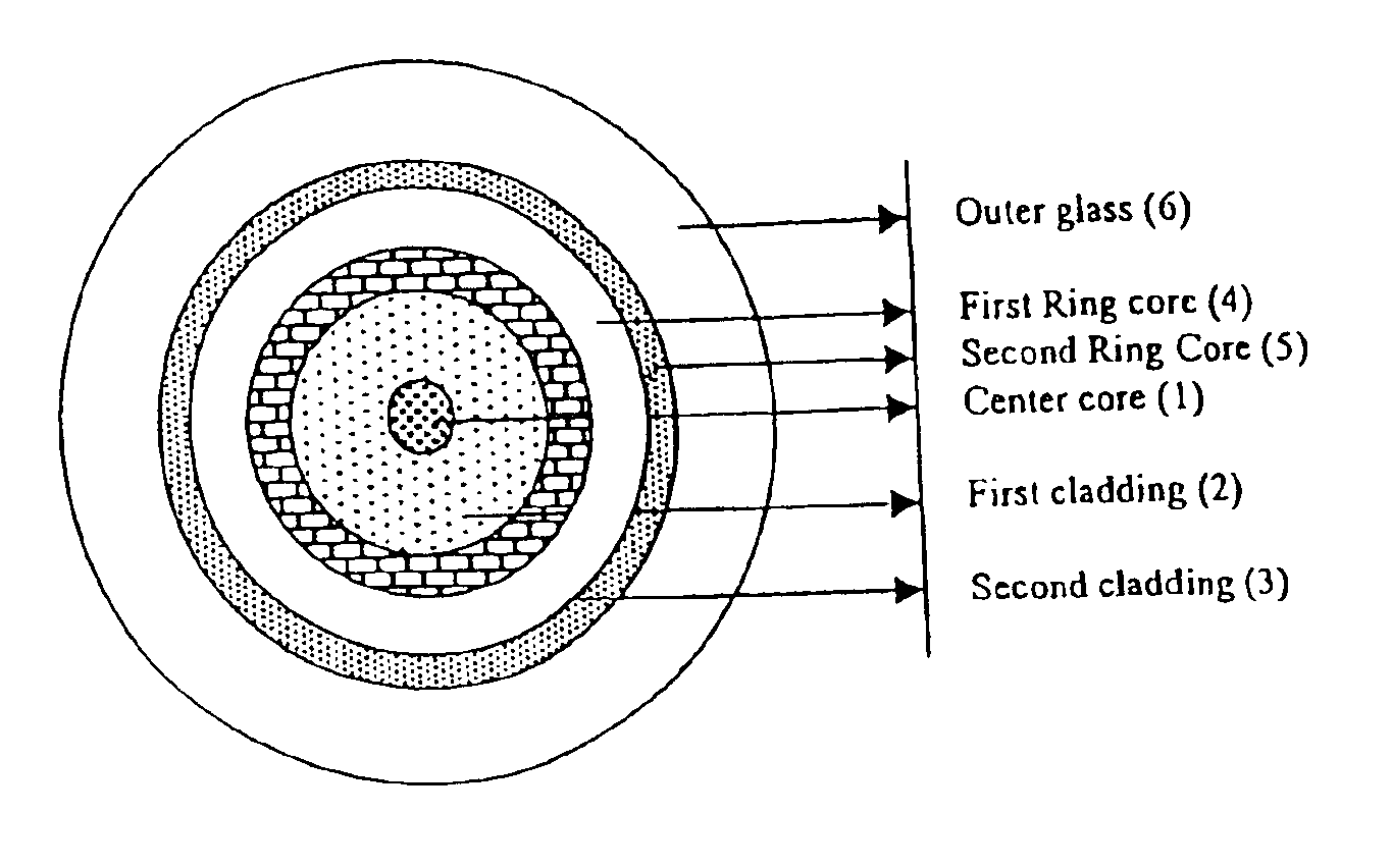
Dispersion shifted fiber having low dispersion slope comprising a center core, two claddings, a ring core and the outer glass region, wherein the first cladding is provided onto the outer periphery of the center core, the second cladding is provided onto outer periphery of the first cladding and the ring core is provided onto outer periphery of the second cladding, and the outer glass region surrounds the ring core, and the center core and the ring core have higher refractive indices, and the claddings have lower refractive indices than the outer glass region, and the refractive indices are constrained by the equation n1>n4>n5>n2>n3. In accordance with preferred embodiment the fiber comprises of a center core, two claddings, two ring cores, and an outer glass region, wherein the first cladding is provided onto the outer periphery of the center core, the second cladding 3 is provided onto the outer periphery of the first cladding, the first ring core is provided onto the outer periphery of the second cladding, the second ring core 5 is provided onto the outer periphery of the first ring core and the outer glass region surrounds the second ring core, and the refractive indices are constrained by the equation n1>n4>n5>n6>n2>n3.

Description

TECHNICAL FIELD OF THE INVENTIONThe present invention relates to dispersion shifted fiber having low dispersion slope, particularly it relates to dispersion optimized fiber having low dispersion slope between 1530 to 1565 nm (C-band) and 1565 to 1625 nm (L-band) transmissions. More particularly it relates to single mode dispersion optimized fiber, which is suitable for transmission of higher bandwidth over longer distance with more uniform chromatic dispersion over the third and fourth window and yet has optimized mode field diameter to achieve low bending induced loss at 1550 nm and at the more critical 1600 nm wavelength.BACKGROUND ART OF THE INVENTIONOver the last decade, the optical fibers have been developed and installed as the backbone of interoffice networks for voice, video and data transmission. These are becoming important with growing and expanding telecommunication infrastructure. Their importance is further increasing because of their high bandwidth applicability. The ...

Claims


Application Information

Patent Timeline
Patent Type & Authority Patents(United States)
IPC IPC(8): G02B6/036G02B6/02
CPCG02B6/02242G02B6/02271G02B6/03688G02B6/03672G02B6/02285
Inventor CHANGDAR, SAMARESHDAS, STHITADHI
Owner STERLITE TECHNOLOGIES
Learn More