
Actuating device, particularly for actuating locking differentials on vehicles

a technology for locking differentials and actuators, which is applied in the direction of electrical apparatus, mechanical equipment, dynamo-electric machines, etc., can solve the problems of reducing the number of tolerances which go into the resulting air gap, and achieve the effect of saving components and machining steps and being produced very inexpensively

Inactive Publication Date: 2005-04-12
VALEO MOTOREN & AKTUATOREN
View PDF12 Cites 7 Cited by
  • Summary
  • Abstract
  • Description
  • Claims
  • Application Information

AI Technical Summary

Benefits of technology

The provision of a sensor unit to measure the angle of rotation has the advantage that the exact position of the actuating shaft can be determined. To shift the locking differential, for example, precisely, it is necessary to specify or to establish exactly the angle of rotation of the actuating shaft.
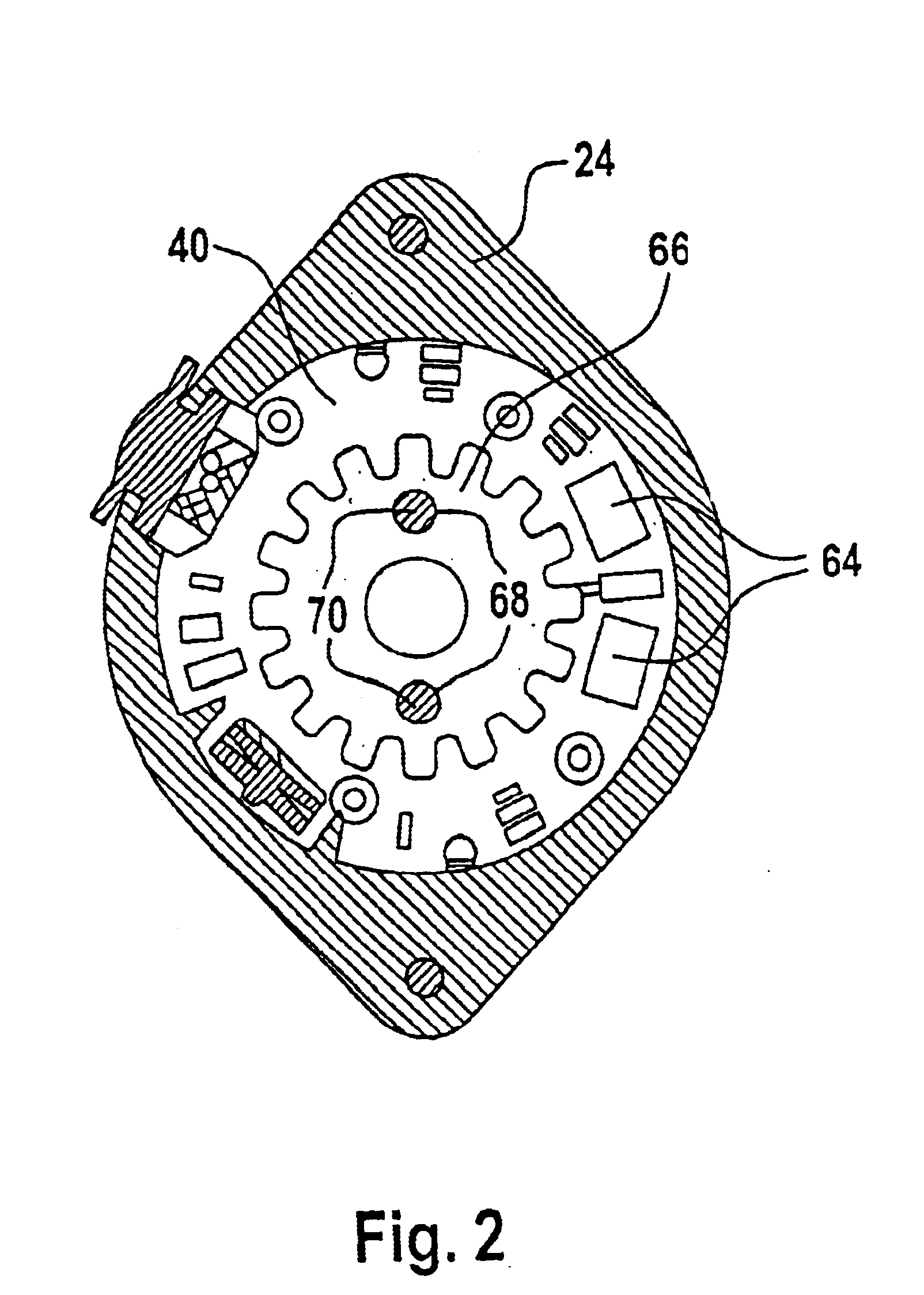
Advantageously the bars, or annular segments, of the commutator form the trigger wheel. The bars, or annular segments, then have to be of an appropriate material. An aspect of the invention such as this has the advantage that an additional trigger wheel is not needed, which saves components and machining steps. Direct scanning of the bars or annular segments of the commutator takes place advantageously in the area of the weld spots.

Problems solved by technology

This reduces the number of tolerances which go into the resulting air gap between the rotating trigger wheel and the stationary sensor.

Method used


Image

  • Actuating device, particularly for actuating locking differentials on vehicles
  • Actuating device, particularly for actuating locking differentials on vehicles
  • Actuating device, particularly for actuating locking differentials on vehicles

Examples


Embodiment Construction

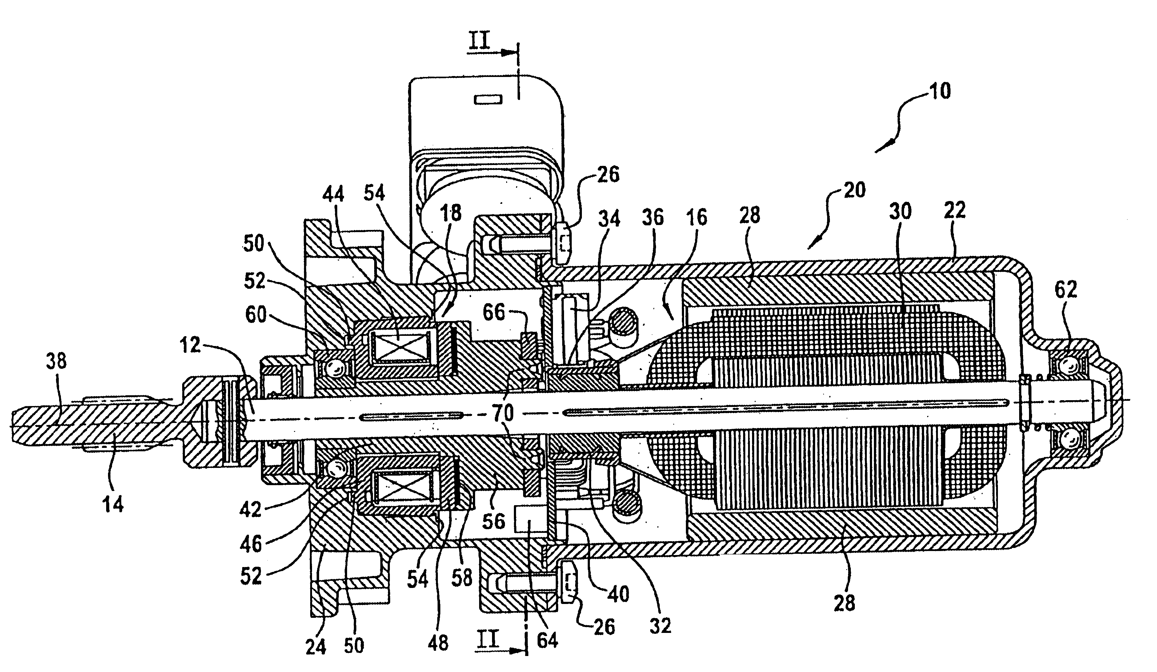
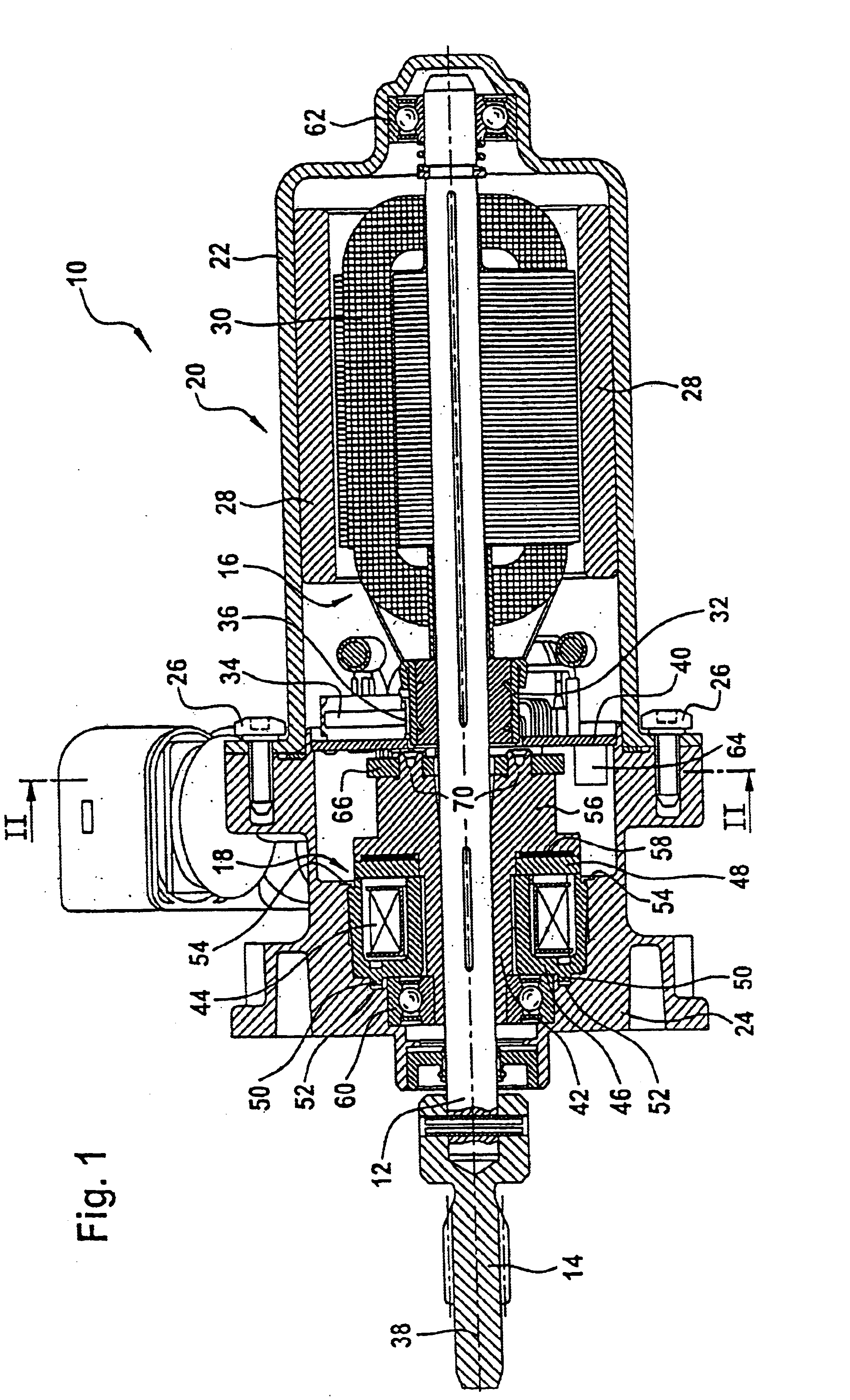
A first aspect of an actuating device 10 of the invention is shown in FIG. 1. The actuating device 10 has a pinion 14 on the free end of an actuating shaft 12, by means of which a locking differential, which is not shown, on a vehicle can be actuated. The actuating device comprises a drive unit 16 and an electromagnetic brake unit 18, where the drive unit 16 and the brake unit 18 are accommodated in a common housing 20. The housing 20 comprises a pot-shaped housing base 22, which positions the drive unit 16. The housing further comprises a housing cover 24, in which the brake unit 18 is located. The housing cover 24 can be tightly bolted to the housing base 20 by means of fasteners 26.

The drive unit 16 includes permanent magnets 28 on the housing side which interact with an armature core 30 attached to the actuating shaft 12 so as not to rotate. The drive unit 16 further comprises a commutator 32, attached to the actuating shaft so as not to rotate, against whose outer surface brush...


PUM


Abstract

An actuating device, specifically for actuating locking differentials on vehicles, having an actuating shaft, a drive unit to drive the actuating shaft, where the drive unit comprises an armature core mounted to the actuating shaft so as not to rotate, and a commutator mounted to the actuating shaft so as not to rotate and / or with an electromagnetic brake unit to slow and / or stop the actuating shaft, where the brake unit includes a brake hub flange mounted on the armature so as not to rotate and having a single- or multi-piece housing tightly enclosing the drive unit and the brake unit, where the free end of the actuating shaft extends from the housing and with a sensor to measure the angle of rotation of the shaft, where the sensor unit includes at least one trigger wheel indirectly coupled to the shaft and at least one sensor scanning the trigger wheel position and coupled indirectly to the housing.

Description

BACKGROUNDThe invention relates to an actuating device, particularly for actuating locking differentials on vehicles.Actuating devices of this type find an application particularly in a vehicle to assist the drive and brake systems. Such devices normally comprise a drive unit to drive an actuating shaft and a brake unit to slow the actuating shaft. A locking differential can be engaged or disengaged by means of the actuating shaft. The drive unit performs the actual shifting action. The brake unit keeps the actuating shaft in a predetermined position.Severe demands are placed on actuating devices of this type. In particular they must withstand operating temperatures of several hundred degrees Celsius. The actuating shaft can be subject to only relatively minor play so that it can ensure functionally reliable actuation of the locking differentials. In addition, the actuating shaft should be of uncomplicated construction and be simple to install. The actuating shaft should also be of ...

Claims


Application Information

Patent Timeline
Patent Type & Authority Patents(United States)
IPC IPC(8): H02K7/10H02K7/102H02K5/14H02K11/00F16D28/00H02K11/215
CPCH02K5/148H02K11/0021H02K7/1025H02K11/215
Inventor FREY, RONALDSCHMIDT, HARALDHELMICH, JOHANNESSCHEYTT, BIRGITBAESKOW, WERNER
Owner VALEO MOTOREN & AKTUATOREN
Learn More