Filter material and method of making same

a filter material and filter material technology, applied in the field of filter materials, can solve the problems of high pressure drop rendering the product unacceptable for some applications, not clean enough, and mats are “dirty”

Inactive Publication Date: 2005-04-12
DMARK
View PDF25 Cites 21 Cited by
  • Summary
  • Abstract
  • Description
  • Claims
  • Application Information

AI Technical Summary

Benefits of technology

I have found that a very effective light duty filter may be made having a thickness of between ⅛ inch to ⅜ inch composed entirely of low melt fibers of a 4 to 15 denier with sorbtive particles distributed uniformly through the web or mat and being of a size ranging from about 20 / 50 to 30 / 80 mesh. While I mentioned in the U.S. Pat. No. 5,569,489 patent that low melt fibers might be used with structural fibers, I believe the use of solely low melt fibers in the light duty type filter is a new concept. It virtually eliminates shedding and is essentially the opposite approach of U.S. Pat. No. 5,569,489.

Problems solved by technology

While this helped lock the sorbtive particles in the mat, though not as completely as desired, it caused a high pressure drop rendering the product unacceptable for some applications.
The failure to lock the particles in the mat completely, rendered the mat “dirty”, i.e., not clean enough for some applications.

Method used


Image

  • Filter material and method of making same
  • Filter material and method of making same
  • Filter material and method of making same

Examples


Embodiment Construction

)

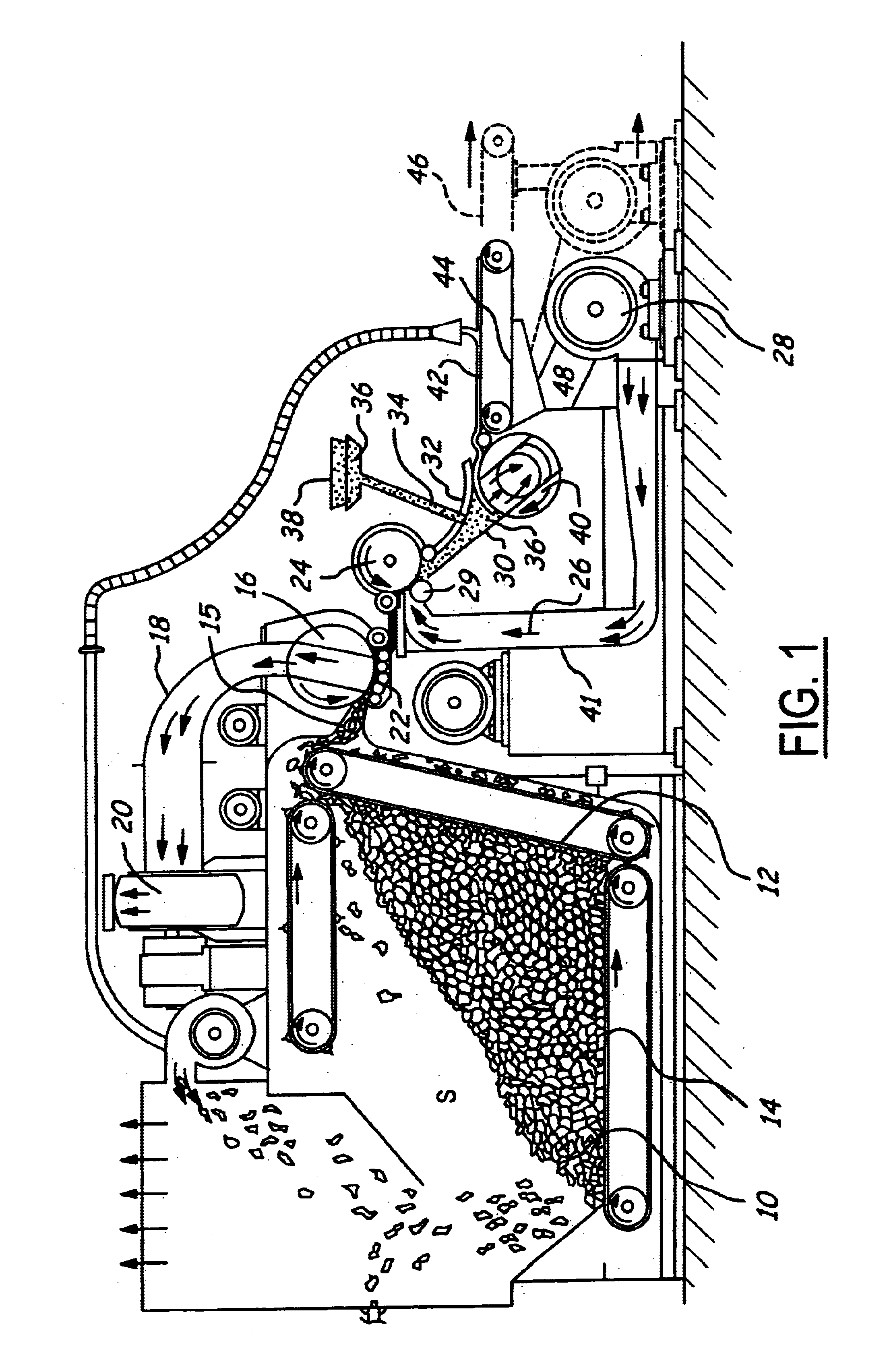
In FIG. 1, apparatus is schematically shown for making filter material as described herein and comprises a chamber S containing a quantity of non woven random fibers 10. These fibers 10 are moved toward a conveyor 12 by a conveyor 14. Conveyor 12 moves the fibers upwardly where they sweep across an air bridge 15 and against a feed mat condenser screen 16 against which they are drawn by a partial vacuum in a suction pipe 18 connected to the suction side of an air pump 20. At the condenser 16 the fibers are matted at 22 and the matt passes to a lickerin 24 where it encounters an air stream 26 provided by air pump 28. At the lickerin 24 the fibers enter the air stream 26 at the saber 29 and pass downwardly at an angle through the venturi duct 30 beneath the duct cover 32. At the lickerin 24 the fibers in the mat formed at the condenser screen 16 are separated and fly as individual fibers into the venturi duct 30. Details of construction and operation of the apparatus as thus far descr...


PUM

PropertyMeasurementUnit
thicknessaaaaaaaaaa
thicknessaaaaaaaaaa
sizeaaaaaaaaaa

Abstract

Non-shedding light duty fibrous filter material containing activated carbon and/or other sorbtive granules is disclosed having a thickness of ⅛ inch to ⅜ inch and composed entirely of low melt fibers of 4 to 15 denier. Heavy duty filter material, also of a non-shedding clean character, is of ¾ to 1 inch thickness and comprises a mixture of 70% structural fibers and 30% low melt fibers.

Description

BACKGROUND OF THE INVENTION1. Field of the InventionThis invention relates to filter material for use in removing by adsorption or absorption (sorbtion) undesirable matter from a fluid stream which passes through the filter material. Also disclosed are methods of making the filter material in a production setting.2. Background ArtThis application incorporates by reference U.S. Pat. Nos. 5,338,340 and 5,569,489.In U.S. Pat. No. 5,569,489, I have disclosed methods of making filter material wherein sorbent particles or granules are incorporated into a fibrous mat during the formation of the mat. Further experimentation with such methods of making filter material has enabled me to make improvements in the methods which have resulted in the ability to produce in a production setting a wide variety of filter material ranging from about one inch in thickness for heavy duty applications down to about one-eighth inch thickness for light duty applications and wherein the sorbtive particles ar...

Claims


Application Information

Patent Timeline
Patent Type & Authority Patents(United States)
IPC IPC(8): B01D53/02B01D39/16B01D39/20B01J20/28
CPCB01D39/163B01D39/2055B01D53/02B01J20/28038B01J20/28028B01J20/2803B01J20/28004
Inventor KASMARK, JR., JAMES W.
Owner DMARK
Why Eureka
Try Eureka