
Adjustable mirror assembly for polarization dependent loss compensation

a mirror assembly and polarization-dependent technology, applied in the direction of optical radiation measurement, instruments, spectrometry/spectrophotometry/monochromators, etc., can solve the problem of not perfectly balanced net effects of the two halves of the optical spectrum analyzer, and achieve the effect of reducing pdl

Inactive Publication Date: 2005-04-05
AGILENT TECH INC
View PDF1 Cites 1 Cited by
  • Summary
  • Abstract
  • Description
  • Claims
  • Application Information

AI Technical Summary

Benefits of technology

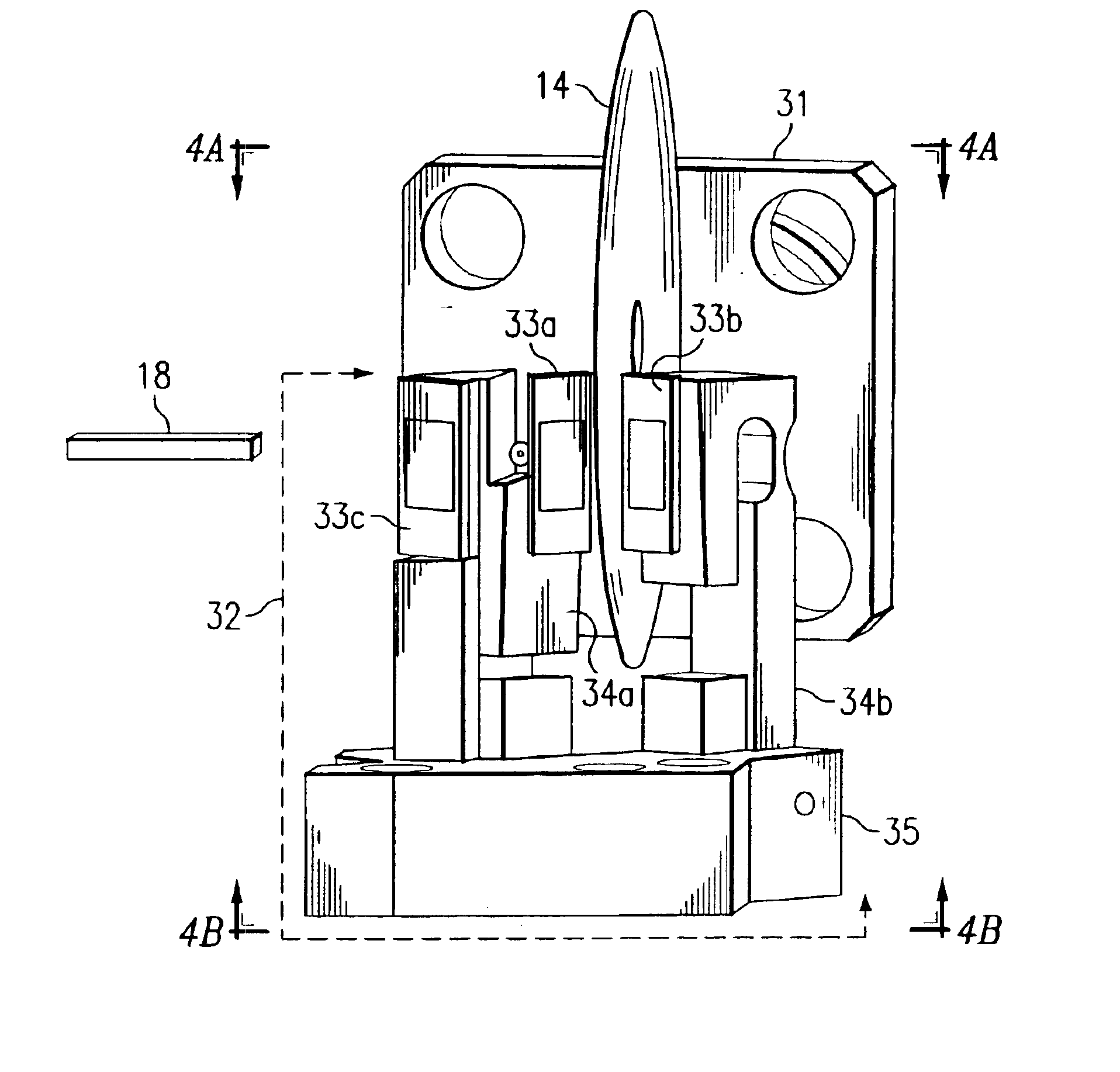
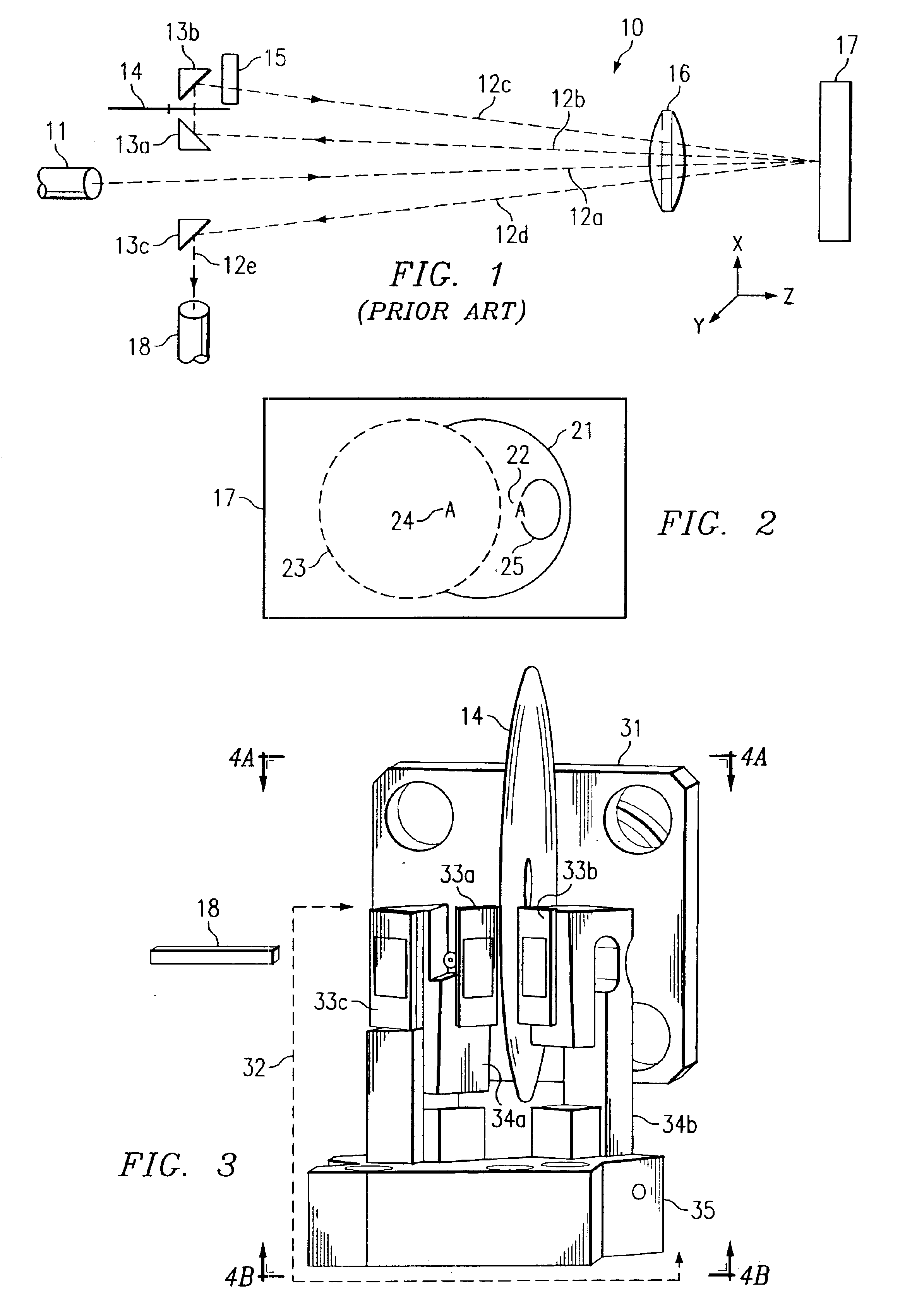
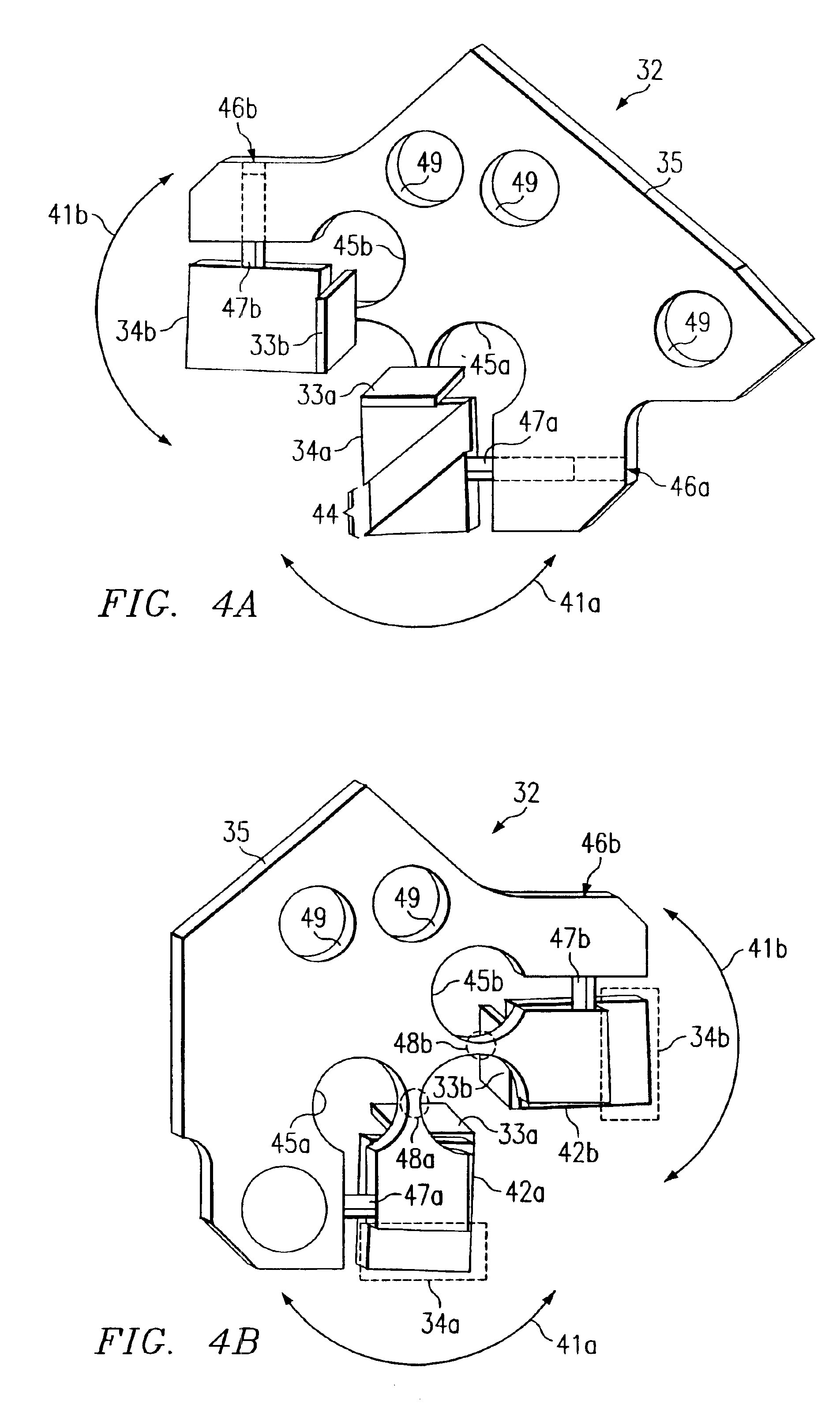
The present invention is directed to a system and a method for compensating polarization dependent loss (PDL) due to propagation through an optical system of an optical beam having a randomly and unpredictably variable input polarization state. The optical system contains a first optical surface, for example a diffraction grating, a first adjustable mirror, and a polarization shifter for interchanging the respective parallel (P) and perpendicular (S) polarization axes of the optical beam relative to the first optical surface, thereby generating a polarization interchanged optical beam having reversed orientations of the S and P polarization components relative to the input. The optical beam is reflected from the first adjustable mirror, which reoptimizes by redirecting the optical beam location on the first optical surface from first pass to second pass, thereby reducing PDL due to propagation through the optical system. In this regard the first optical surface may be considered a variable PDL component. In some embodiments the location of the optical beam relative to the first adjustable mirror remains substantially constant.

Problems solved by technology

This shows that the net effects of the two halves of the optical spectrum analyzer are closely but not perfectly balanced.
These can produce instrument output power fluctuations that may be incorrectly attributed, for example, to source power fluctuations, but in reality may be artifacts produced by instrument PDL.

Method used


Image

  • Adjustable mirror assembly for polarization dependent loss compensation
  • Adjustable mirror assembly for polarization dependent loss compensation
  • Adjustable mirror assembly for polarization dependent loss compensation

Examples


Embodiment Construction

Certain system properties facilitate the polarization rotation scheme described in connection with FIG. 1. One such property is that the first pass 12a, 12b of the system physically have the same effective total component reflectance ratio of S / P polarizations as the second pass 12c, 12d. Individual component reflectance values may vary from first pass to second pass, but their aggregate value as used in the ratio is the same. One way of implementing this method is to make the net component reflectance values from the first pass for S and P polarizations respectively the same as in the second pass. Embedded in this property is the desirability of component spatial uniformity. Any optical beam traveling through the OSA will have some spatial extent over which the optical power is distributed. The term spatial extent means the length and width or physical area of the optical component surface where the light is incident. The term spatial uniformity means that the optical component wil...


PUM


Abstract

An optical beam having a randomly and unpredictably variable input polarization state propagates through an optical system containing a first optical surface, for example a diffraction grating, a first adjustable mirror, and means for rotating the respective parallel (P) and perpendicular (S) plane polarization components of the optical beam relative to the first optical surface by ninety degrees, thereby generating a polarization rotated optical beam having reversed orientations of the S and P polarization components relative to the input. The optical beam is reflected from the first adjustable mirror, which redirects the optical beam onto an optimized location on the first optical surface, thereby reducing PDL due to propagation through the optical system. In some embodiments the optical beam location on the first adjustable mirror remains substantially constant during adjustment.

Description

TECHNICAL FIELDThe present invention relates to polarization dependent loss compensation, and particularly to an adjustable mirror assembly for polarization dependent loss compensation in an optical instrument.BACKGROUND OF THE INVENTIONPolarization dependent loss (PDL), in which optical power transmitted along a propagation path changes as a function of polarization state of the light beam, is a well-known phenomenon in optical systems and instruments, for example optical spectrum analyzers. The maximum difference in power over all possible polarization states is termed polarization dependent loss (PDL). Because changes in polarization state of an input beam occur at an unpredictable time and rate, the optical spectrum analyzer (OSA) or other instrument preferably uses some type of static PDL correction that is not dependent on time or the exact state of polarization of the light that enters the system.FIG. 1 illustrates schematically a current Agilent Technologies 8614x series OSA...

Claims


Application Information

Patent Timeline
Patent Type & Authority Patents(United States)
IPC IPC(8): G01J3/02G01J3/00
CPCG01J3/02G01J3/0202G01J3/0237G01J3/0224G01J3/021
Inventor CLARK, STEPHAN R.FERNANDEZ, LUCAS M.
Owner AGILENT TECH INC
Learn More