
Mobile communication handset with adaptive antenna array

a mobile communication and antenna array technology, applied in diversity/multi-antenna systems, polarisation/directional diversity, resonant antennas, etc., can solve problems such as multi-path fading, radio signal transmitted from a sender (either a base station or mobile subscriber unit), interference, fading or dropout of received signals, etc., to minimize size and manufacturing complexity, the effect of maximizing the antenna performan

Inactive Publication Date: 2005-04-05
IPR LICENSING INC
View PDF24 Cites 58 Cited by
  • Summary
  • Abstract
  • Description
  • Claims
  • Application Information

AI Technical Summary

Benefits of technology

The intercell interference problem is exacerbated in CDMA systems since the subscriber units in adjacent cells typically transmit on the same carrier or center frequency. For example, two subscriber units in adjacent cells operating at the same carrier frequency but transmitting to different base stations interfere with each other if both signals are received at one of the basse stations. One signal appears as noise relative to the other. The degree of interference and the receiver's ability to detect and demodulate the intended signal is also influenced by the power level at which the subscribed units are operating. If one of the subscriber units is situated at the edge of a cell, it transmits at a higher power level, relative to other units within its cell and the adjacent cell, to reach the intended base stations. But, its signal is also received by the unintended base station, i.e., the base station in the adjacent cell. Depending on the relative power level of two same-carrier frequency signals received at the unintended base station, it may not be able to properly differentiate a signal transmitted from within its cell from the signal transmitted from the adjacent cell. A mechanism is required to reduce the subscriber units antenna's apparent field of view, which can have a marked effect on the operation of the reverse link (subscriber to base) by reducing the number of interfering transmissions received at a base station. A similar improvement in the antenna pattern for the forward link, allows a reduction in the transmitted signal power to achieve a desired receive signal quality.
In summary, it is clear that in the wireless communications technology, it is of utmost importance to maximize antenna performance, while minimizing size and manufacturing complexity.
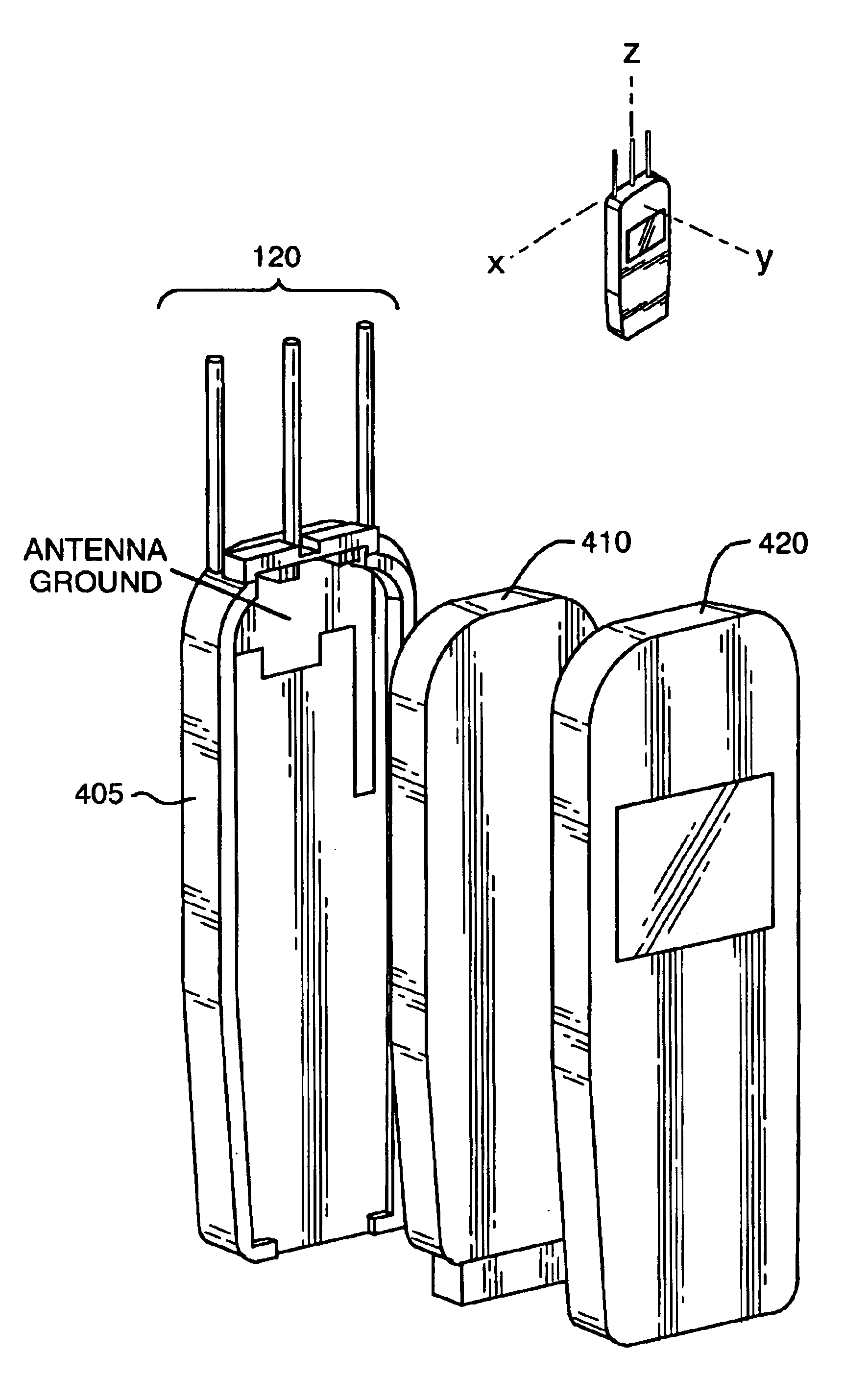
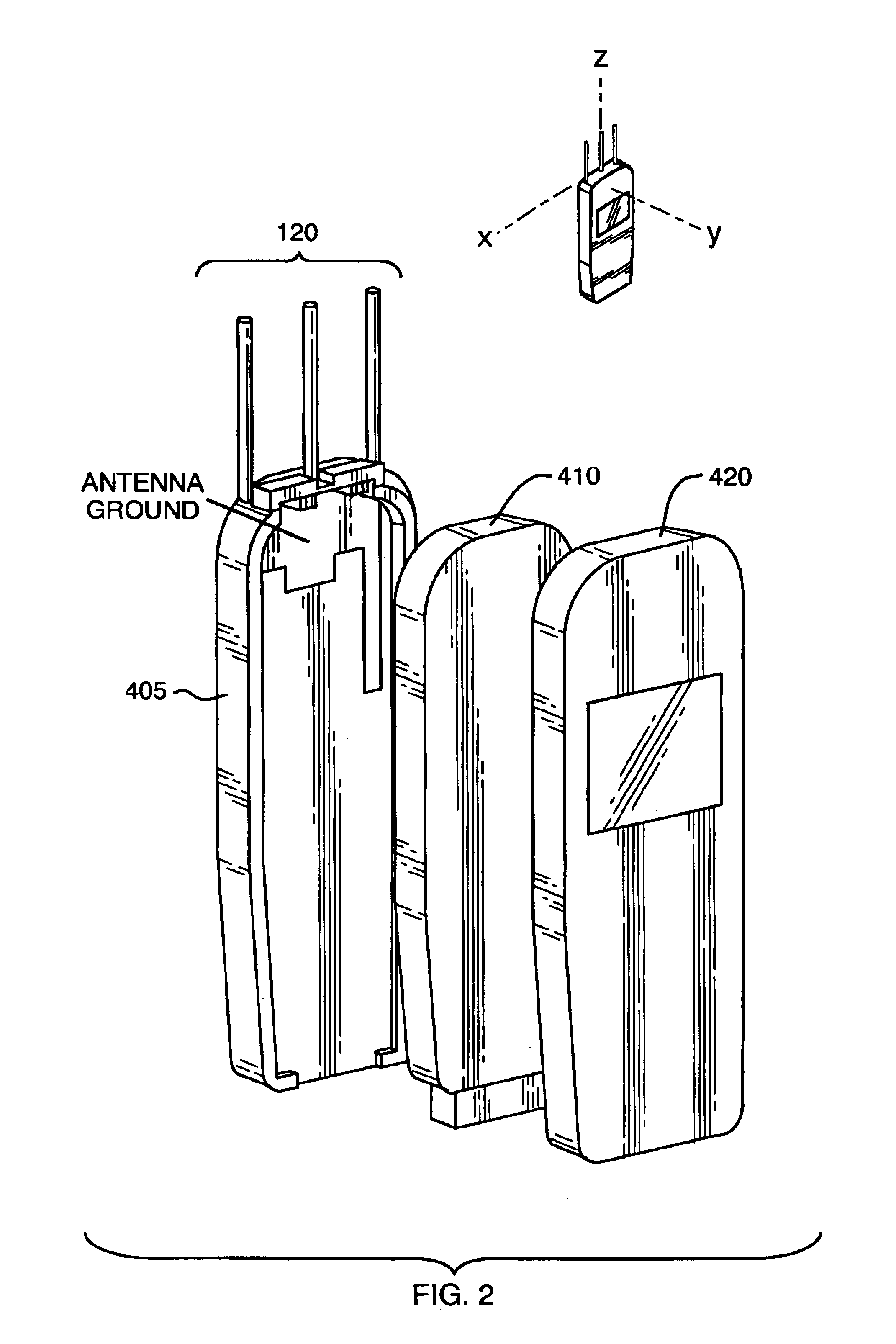
In particular embodiments, the ground structure may have a shape that localizes current or near fields of the antenna elements toward the base of the antenna elements. In this way, negative performance effects imposed by the a human hand holding the handset or the body of the handset itself can be reduced.

Problems solved by technology

One such problem is called multipath fading.
In multipath fading, a radio signal transmitted from a sender (either a base station or mobile subscriber unit) may encounter interference in route to the intended receiver.
As a result, the original and reflected signals may partially cancel each other out (destructive interference), resulting in fading or dropouts in the received signal.

Method used


Image

  • Mobile communication handset with adaptive antenna array
  • Mobile communication handset with adaptive antenna array
  • Mobile communication handset with adaptive antenna array

Examples


Embodiment Construction

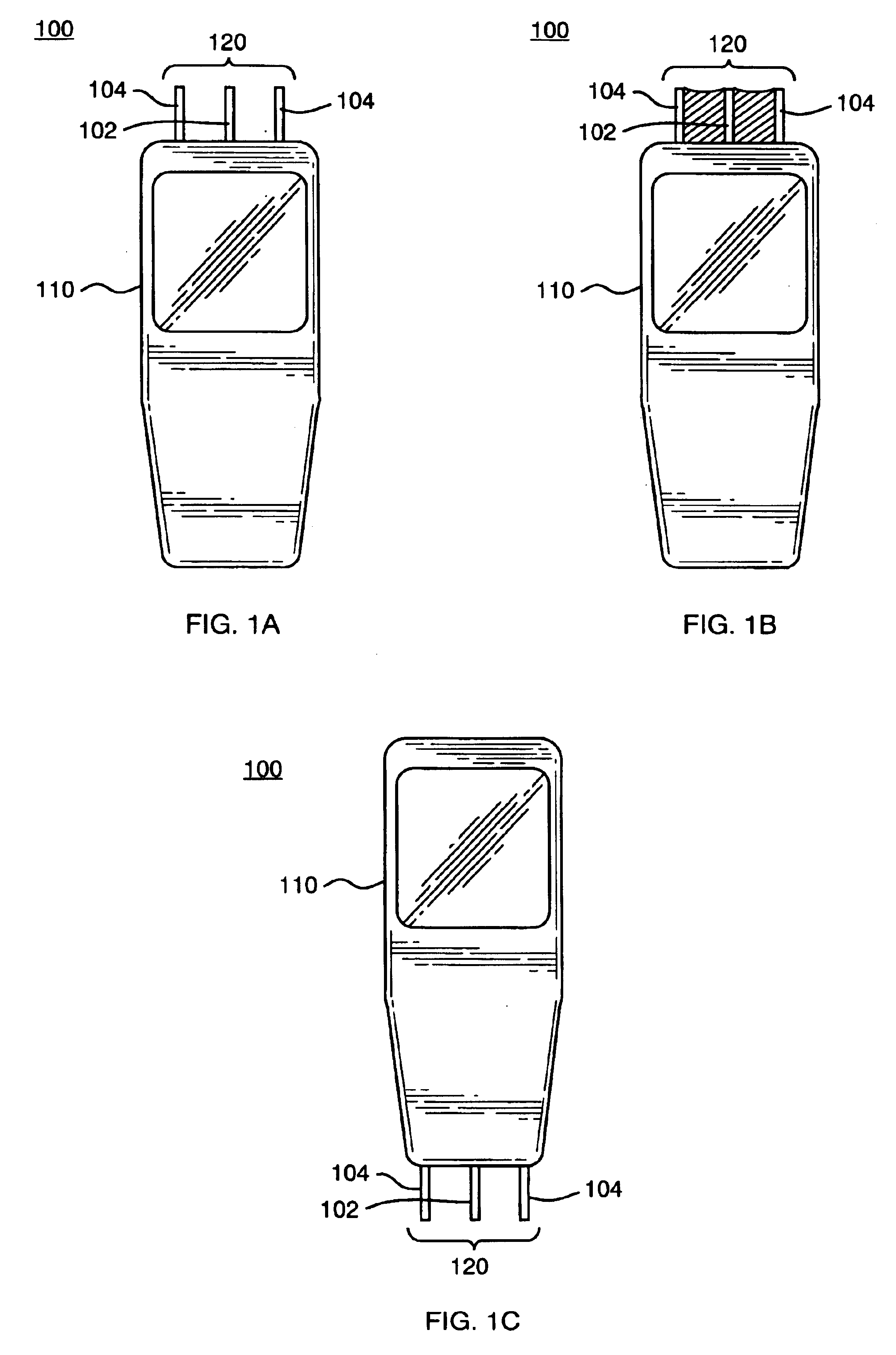
FIGS. 1A, 1B, 1C are high level schematic diagrams of wireless communication devices incorporating a three-element adaptive directional antenna array according to various embodiments. In general, the devices 100 are some form of wireless communications device, such as a mobile communication handset (e.g., cellular handset) or a personal digital assistant (e.g., Palm Pilot). Each device 100 includes a housing 110 having incorporated therein an antenna array 120.

The antenna array 120 provides for directional reception and transmission of radio communication signals with a base station, in the case of a cellular handset 100, or from an access point, in the case of a wireless data unit 100 making use of wireless local area network (WLAN) protocols. By directively communicating signals with a particular base station and / or access point, the antenna array 120 assists in reducing the overall effect of intercell interference and multipath fading for the mobile unit 100. Moreover, as will be...


PUM


Abstract

A mobile communication handset includes at least one passive antenna element and an active antenna element adjacent to the passive antenna elements protruding from a housing. The active element is coupled to electronic radio communication circuits and the passive antenna elements are coupled to circuit elements that affect the directivity of communication signals coupled to the antenna elements.

Description

BACKGROUND OF THE INVENTIONCode Division Multiple Access (CDMA) modulation and other spread spectrum techniques now find widespread application in wireless systems such as cellular mobile telephones, wireless local area networks and similar systems. In these systems a connection is provided between a central hub or base station and one or more mobile or remote subscriber units. The base station typically includes a specialized antenna for sending forward link radio signals to the mobile subscriber units and for receiving reverse link radio signals transmitted from the mobile units. Each mobile subscriber unit also contains its own antenna for the reception of the forward link signals and for transmission of reverse link signals. A typical mobile subscriber unit may for example, be a digital cellular telephone handset or a personal digital assistant having an incorporated cellular modem, or other wireless data device. In CDMA systems, multiple mobile subscriber units are typically tr...

Claims


Application Information

Patent Timeline
IPC IPC(8): H01Q19/00H01Q3/44H01Q19/32H01Q1/24H01Q3/24H01Q3/00H04B1/38H04B7/10
CPCH01Q1/242H01Q1/245H01Q3/24H01Q19/32H01Q9/16H01Q9/30H01Q19/30H01Q3/44H01Q1/24H04B1/38H01Q3/26
Inventor CHIANG, BINGSNYDER, CHRISTOPHER A.GOTHARD, GRIFFIN K.JORGENSON, DAVID C.
Owner IPR LICENSING INC
Learn More