
Weight lifting device

a weight lifting device and dumbbell technology, applied in the field of barbells, dumbbells and weight lifting devices, can solve the problems of inability to completely guarantee the securing mechanism of the prior art, the weight plate can be extremely heavy, and the handle and the bar do little to enhance the overall appearance of such weight lifting devices

Inactive Publication Date: 2005-04-05
BRICE JOHN P
View PDF14 Cites 41 Cited by
  • Summary
  • Abstract
  • Description
  • Claims
  • Application Information

AI Technical Summary

Benefits of technology

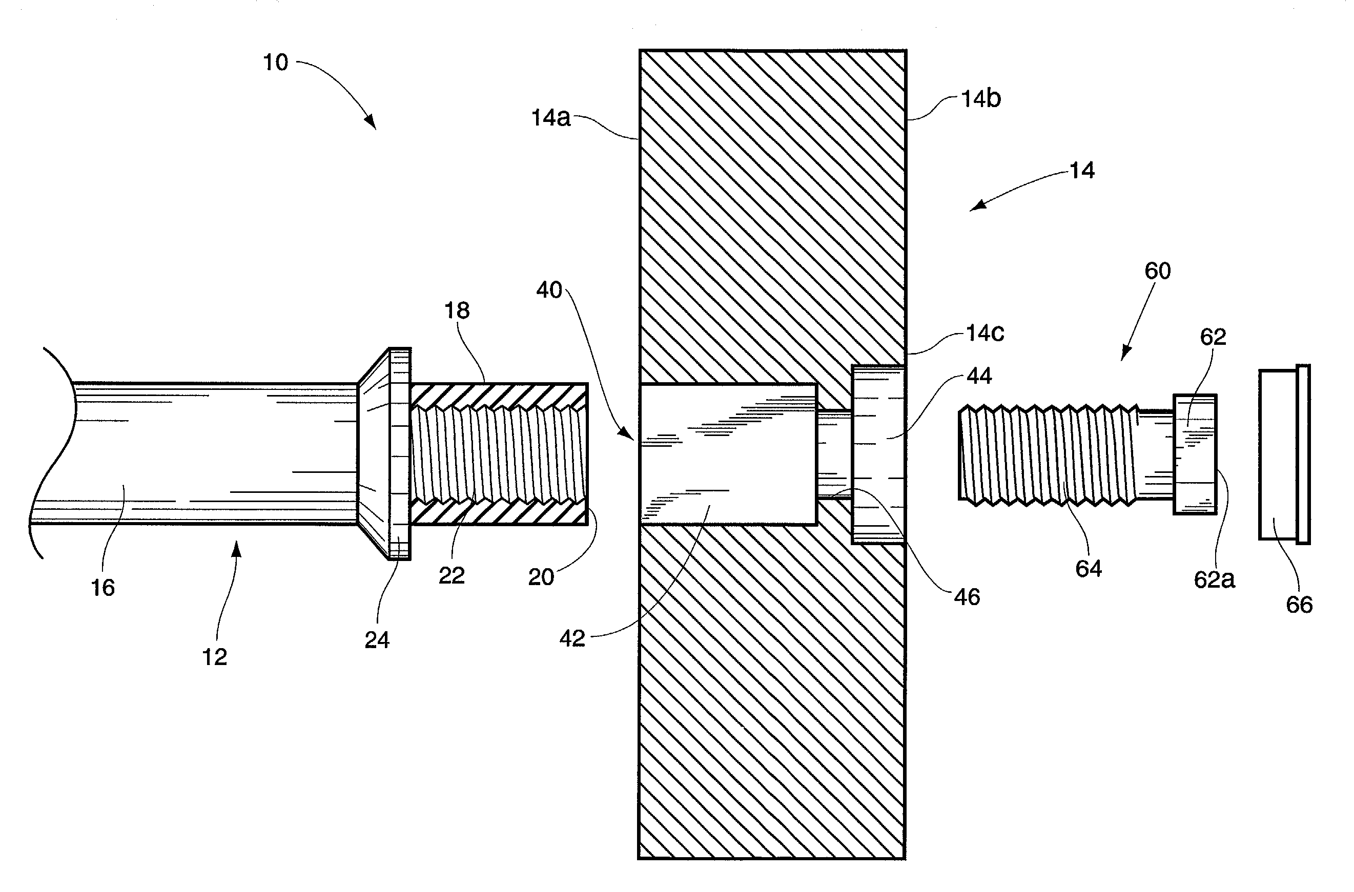
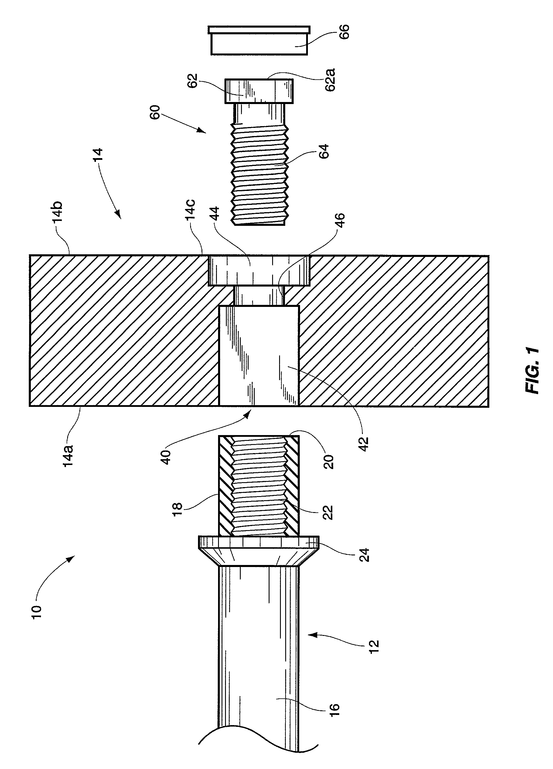
In another particular embodiment of the present invention, the opening formed through the weight plate includes three areas. It includes a receiving area for receiving the end portion of the handle. A second area is referred to as a recessed area since it receives the bolt head and effectively enables the bolt head to be recessed within the weight plate. A third area is referred to as a shoulder. The shoulder partially divides the receiving area from the recessed area. When the bolt is securely tightened within the threaded bore in the end portion of the handle, the bolt head will engage and abut against the shoulder, thereby limiting the inward movement of the bolt head and at the same time pulling the end portion of the handle snugly against the shoulder. Optionally, an end cap can be provided to fit over the recessed bolt head when the weight plate has been secured to the handle or bar.

Problems solved by technology

Simply put, weight plates can be extremely heavy and if they inadvertently fall from a bar or handle, it is certainly possible that an injury may result.
In addition, the securing mechanisms traditionally used to secure weight plates to handles and bars do very little to enhance the overall appearance of such weight lifting devices.
In the end, securing mechanisms of the prior art are not always totally reliable and even the more reliable ones do very little to enhance the overall appearance and design of the weight lifting device.

Method used


Image

  • Weight lifting device
  • Weight lifting device
  • Weight lifting device

Examples


Embodiment Construction

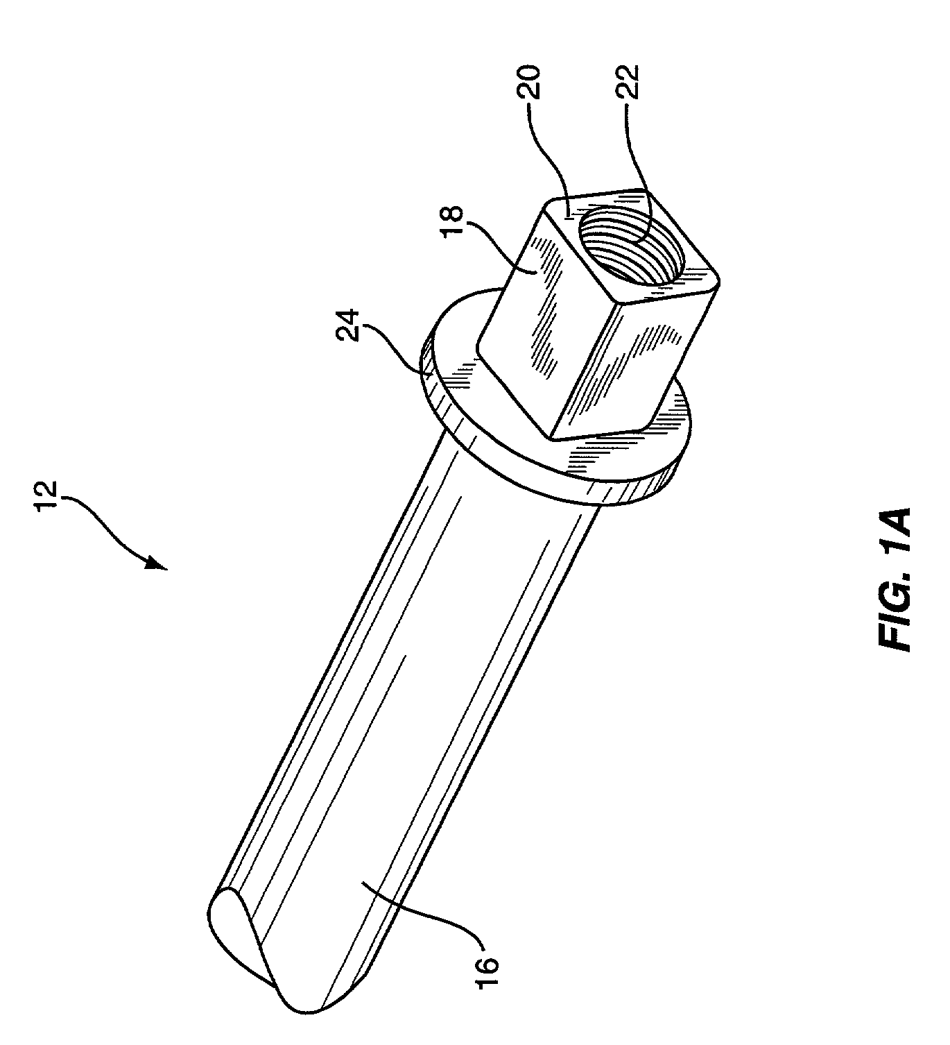
With reference to the drawings, the weight lifting device of the present invention is shown therein and indicated generally by the numeral 10. Weight lifting device 10 includes a handle indicated generally by the numeral 12. In some cases, the handle 12 is referred to as a bar. Further, the weight lifting device 10 is adapted to receive and support a number of weight plates. Each weight plate is indicated generally by the numeral 14.

First, discussing the handle 12, the handle includes a central portion 16 that extends between a pair of inside collars 24. Collars 24 are formed on the handle and remain fixed. The collars 24 can assume various shapes. For example, the collars 24 can match the weight plate and could include 14 sides or simply be round. Disposed about each end of the handle 12 is a pair of end portions indicated by the numeral 18. Each end portion 18 in the case of this embodiment, extends from the adjacent inside collar 24 outwardly. Each end portion 18 includes a ter...


PUM


Abstract

A weight lifting system including a handle or bar that is adapted to be connected to a weight plate. The weight plate includes a central opening that extends through the weight plate. One end portion of the handle is inserted into one end of the opening within the weight plate. A bolt is extended into the opening of the weight plate, from the opposite side, and threaded into a threaded bore formed axially within the end portion. A shoulder is formed intermediately within the opening of the weight plate. As the bolt is turned and threaded into the threaded bore, the end portion of the handle is drawn towards the shoulder while a head portion of the bolt moves towards the shoulder. By securely tightening the bolt within the threaded bore, the bolt head is brought into contact with the shoulder and thereby the inward movement of the bolt is limited. The opening in the weight plate and the bolt are sized such that when the bolt is securely tightened within the threaded bore of the end portion of the handle, the head of the bolt will be recessed within the opening of the weight plate and will not protrude past the adjacent side of the weight plate. To conceal the bolt head and the bolt, a cap can be secured to the end of the opening adjacent the bolt head.

Description

FIELD OF THE INVENTION The present invention relates to barbells, dumbbells and weight lifting devices in general, and more particular to a method and apparatus for securing a weight plate to a barbell, dumbbell or handle of a weight lifting device. BACKGROUND OF THE INVENTION The basic design of barbells and dumbbells and other free weight weightlifting devices are well known and appreciated. Typically, a handle or bar is inserted through a central opening within one or more weight plates. An inside collar is usually secured or fixed to the handle or bar inboard the one or more weight plates on each end of the bar or handle. About the outboard side of the one or more weights, there is usually provided another collar that is secured to the handle or bar. Thus, about each end of the handle or bar there is secured one or more weight plates between two spaced apart collars. Safety is of paramount concern in securing weight plates to a handle or bar. It is, of course, important to retai...

Claims


Application Information

Patent Timeline
Patent Type & Authority Patents(United States)
IPC IPC(8): A63B21/06A63B21/072
CPCA63B21/0728A63B21/0724
Inventor BRICE, JOHN P.
Owner BRICE JOHN P
Learn More