Cooling system for a small watercraft

a technology for cooling systems and watercraft, applied in vessel construction, special-purpose vessels, steam power plants, etc., can solve problems such as water remaining in parts, further damage, and water may remain in water channels, and achieve the effect of preventing accumulated cooling water from remaining in water channels

Inactive Publication Date: 2005-04-05
HONDA MOTOR CO LTD
View PDF3 Cites 4 Cited by
  • Summary
  • Abstract
  • Description
  • Claims
  • Application Information

AI Technical Summary

Benefits of technology

An object of the present invention is to provide a cooling system for a small watercraft, which is capable of draining virtually all the water from the watercraft during storage, and thereby substantially prevents accumulated cooling water from remaining in a water channel.
Therefore, corrosion or freezing in the water channel may be significantly prevented.
Therefore, the effort which would otherwise be required, to drain the plurality of portions where water normally tends to remain, may be significantly alleviated.

Problems solved by technology

In some watercraft according to the prior art, there has been a problem in that when the small watercraft is shored and stored, water may remain in portions of the engine or piping, and the portions having water remaining therein may corrode.
In winter, the trapped water may freeze, which can cause further damage such as burst pipes or other problems.

Method used


Image

  • Cooling system for a small watercraft
  • Cooling system for a small watercraft
  • Cooling system for a small watercraft

Examples


Embodiment Construction

Throughout the following description, expressions of “front”, “rear”, “left”, and “right” denote the directions viewed from the vantage point of a driver.

Referring now to the drawings, a specific illustrative embodiment of the present invention will be described.

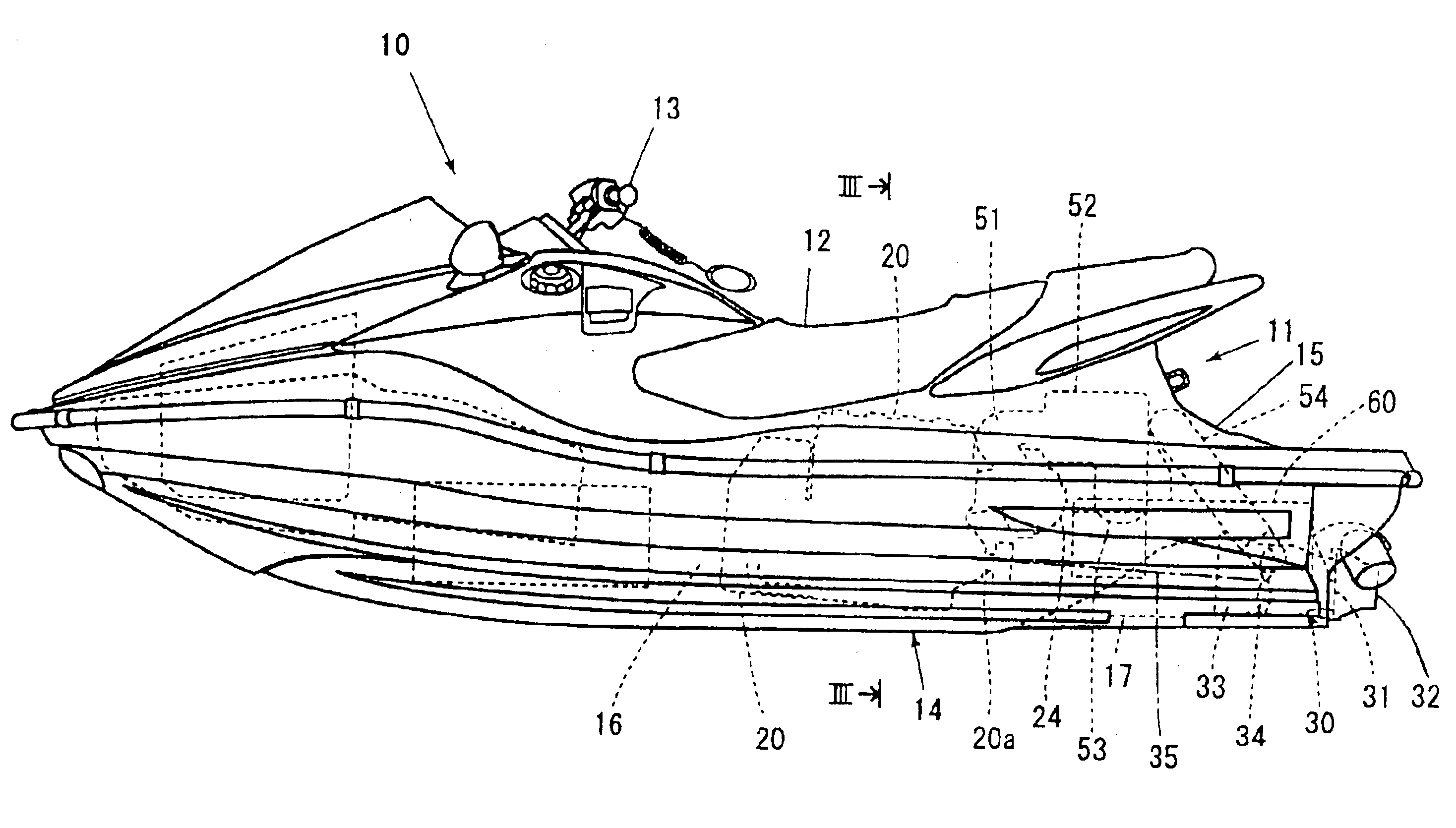
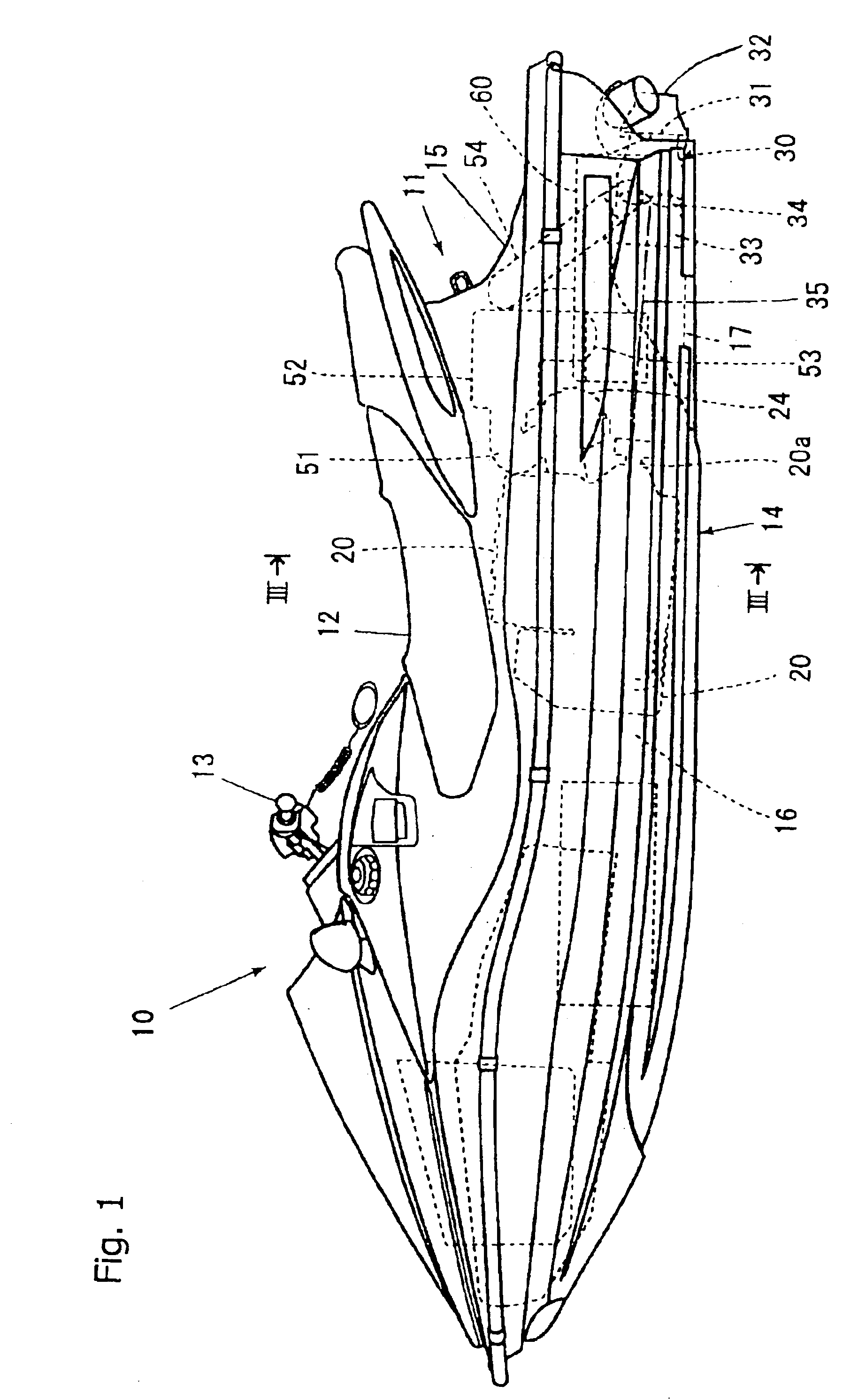
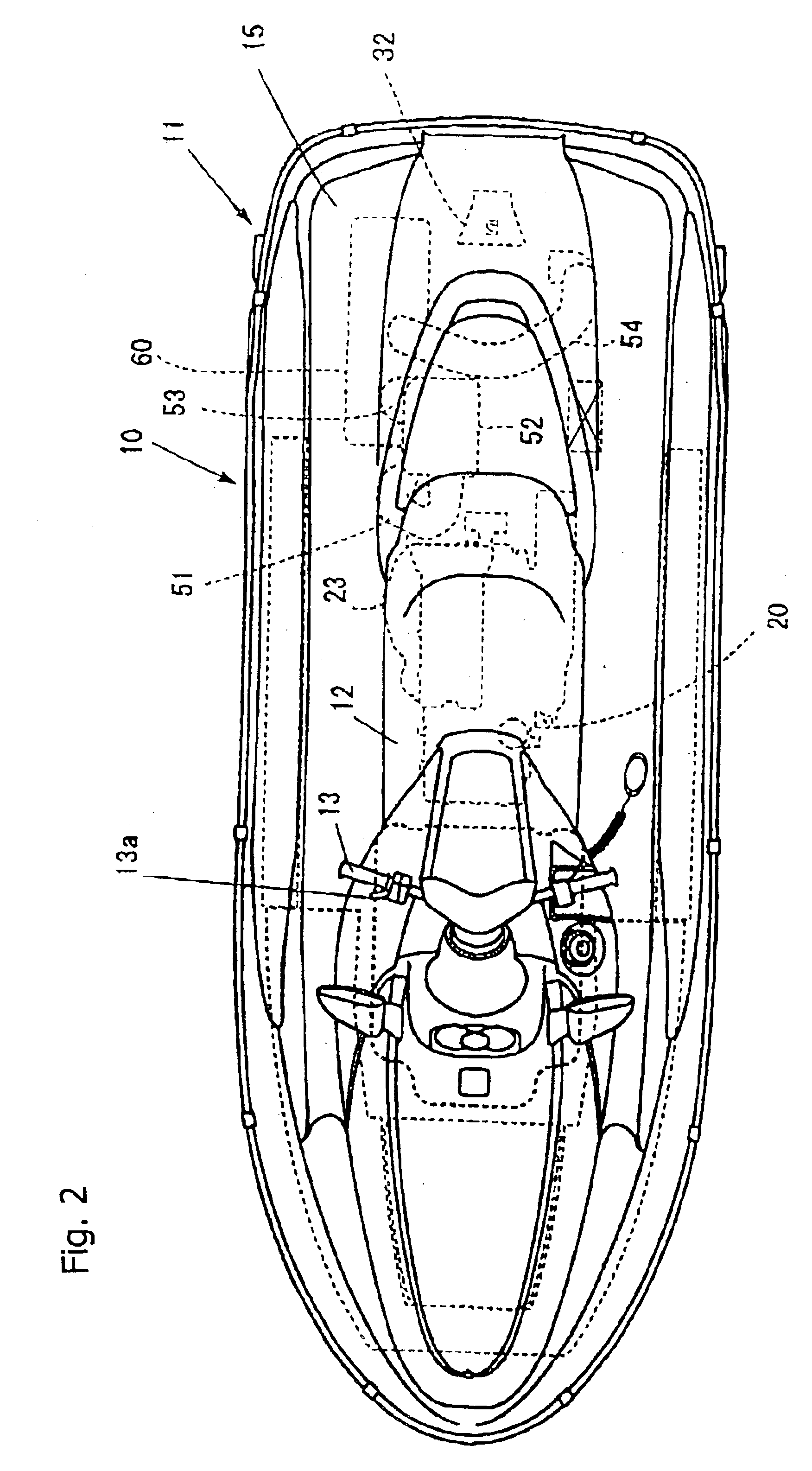
As shown in the drawings (mainly in FIG. 1), a small watercraft 10 is a saddle riding type small watercraft in which a boater is able to sit on a seat 12 of a vessel body 11, and in which a boater is able to operate the watercraft 10 while gripping a steering handle 13 with a throttle lever thereon.

The vessel body 11 is a floating structure formed by joining a hull 14 and a deck 15 on top of the deck, with a hollow interior space 16 defined therebetween. In the interior space 16, an engine 20 is mounted on the hull 14, and a jet pump (jet propulsion pump) 30 is mounted in the rear of the hull 14 as propulsion means. The jet pump 30 is driven by the engine 20 via an impeller shaft 35, which extends therebetween.

The jet pump 3...


PUM


Abstract

A cooling system is provided for a small watercraft which can prevent corrosion or freezing in a water channel. Water outside the watercraft is fed through a pump 30 and piping P1 or the like to a engine in the watercraft and cools the same, and then is drained from the watercraft. Drain hoses DH1 to 3 are connected to portions of the engine and piping where water tends to remain, and drain ports DH1a to 3a, which are capable of being opened and closed, are provided at the other ends of the drain hose. A single drain valve DV is provided at the drain port for opening and closing the drain hose.

Description

CROSS-REFERENCE TO RELATED APPLICATIONSThe present application claims priority under 35 U.S.C. 119, based on Japanese patent application No. 2002-284220, filed Sep. 27, 2002.BACKGROUND OF THE INVENTION1. Field of the InventionThe present invention relates to a cooling system for a small watercraft. More particularly, the present invention relates to a cooling system in which water from outside the watercraft is fed through a pump and piping, to effectively cool an internal-combustion engine in the watercraft.2. Description of the Background ArtA personal watercraft is known as a small size craft that is constructed and arranged to glide on the surface of a sea or lake. Jet skis and other types of small personal watercraft are known and are commercially available.In the boating art, a cooling system for a small watercraft is constructed in such a manner that water outside the watercraft is fed through a jet pump and piping to a engine, which is a heat generating body such as an engin...

Claims


Application Information

Patent Timeline
Patent Type & Authority Patents(United States)
IPC IPC(8): F01P11/00F01P11/02B63B35/73F01P3/20
CPCF01P11/0276F01P2050/04
Inventor NAKAJIMA, JUNMATSUO, HISASHI
Owner HONDA MOTOR CO LTD
Why Eureka
Try Eureka