Transfer tube for carburetor fuel bowls

a technology for carburetor and fuel bowl, which is applied in the direction of heating types, separation processes, applications, etc., can solve the problems of fuel to the carburetor also tending to surge, fuel to the fuel bowl sometimes tending to surge, and the hazard of temporary starvation of fuel from the carburetor, so as to reduce the likelihood of improper installation of the fuel transfer tube

Inactive Publication Date: 2005-04-05
HOLLEY PERFORMANCE PRODUCTS
View PDF14 Cites 20 Cited by
  • Summary
  • Abstract
  • Description
  • Claims
  • Application Information

AI Technical Summary

Benefits of technology

In the preferred embodiment at least two O-ring grooves are formed on each nipple and O-rings are seated in both O-ring grooves of each nipple, interposed between the nipples and each end of the fuel transfer tube. By using a pair of O-rings at each end of the fuel transfer tube, the sealing effect between the ends of the fuel transfer tube and their respective nipples is doubled. Also, O-rings are used in a standard size and shape that are available from the typical auto supply store or hardware store so that if a leakage should occur at one end of a fuel transfer tube, the leaking O-rings can be removed from their nipple, and new O-rings mounted on the nipple.
The fuel transfer tube is of a length so that its ends will extend about the nipples and about the O-ring seals of the external fuel sealing fixtures, so that no adjustment in the length of the fuel transfer tube or in the space between the external fuel sealing fixtures is required, and the likelihood of improper installation of the fuel transfer tube is reduced.

Problems solved by technology

Because a race car experiences extreme surges front to rear and side to side during its performance on the track, the fuel in the fuel bowl that supplies the fuel to the carburetor also tends to surge, so that the fuel in the fuel bowl sometimes tends to surge in the fuel bowl away from the carburetor.
If the outlet port of the fuel bowl is adjacent the carburetor, there is a hazard of temporary starvation of fuel from the carburetor when the fuel surges away from the carburetor.
The sealing sleeve provides only one sealing surface and is subject to damage when the transfer tube is being installed and when the fuel bowls are disassembled for adjustment and repair of the carburetor.
The damaged sealing sleeve tends to leak fuel, and the location of the leak is at the top of the engine.
While the modular attachments simplify assembly, repair and adjustment of carburetors, they have not proven to be leak-proof, sometimes allowing fuel to leak from the carburetor assembly in the vicinity of the hot engine.
It is difficult to repair the leak of this type of transfer tube.
All of the above-noted prior art fuel transfer tube assemblies include the hazard of fuel leakage about the carburetor and the hot engine below.
If there is fuel leakage, these prior art devices are difficult to repair, as by acquiring the proper sealing sleeve that is a special order product, or by repairing the fuel transfer kit.

Method used


Image

  • Transfer tube for carburetor fuel bowls
  • Transfer tube for carburetor fuel bowls
  • Transfer tube for carburetor fuel bowls

Examples


Embodiment Construction

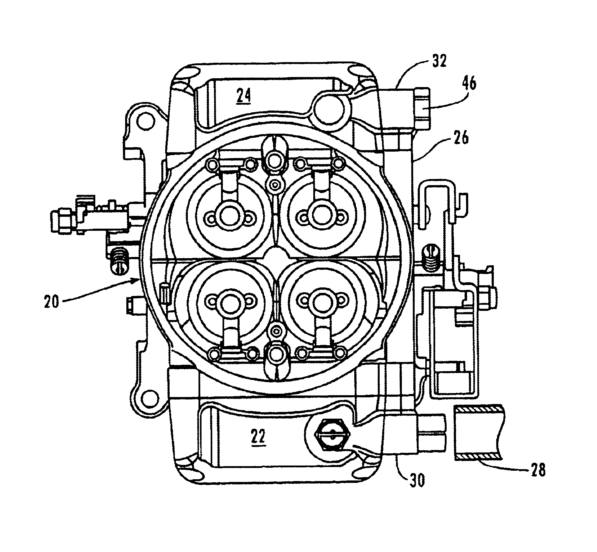
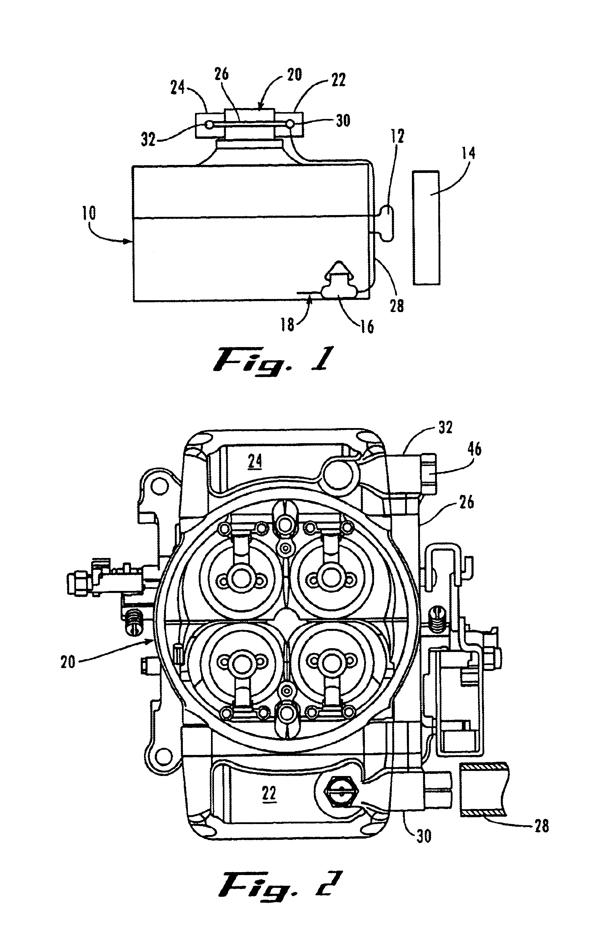
Referring now in more detail to the drawings in which like numerals indicate like parts throughout the several views, FIG. 1 illustrates an internal combustion engine 10 of a high performance vehicle, that includes the usual components such as water pump 12, radiator 14, fuel pump 16 and fuel line 18 extending from the fuel tank (not shown) that is usually mounted at the rear of the vehicle. The carburetor 20 is mounted on the upper surface of the engine 10, with front fuel bowl 22 and rear fuel bowl 24 mounted to the carburetor and with the fuel transfer tube 26 extending between the fuel bowls 22 and 24. The fuel line 28 extends from the fuel pump 16 to one of the fuel bowls, such as fuel bowl 22.

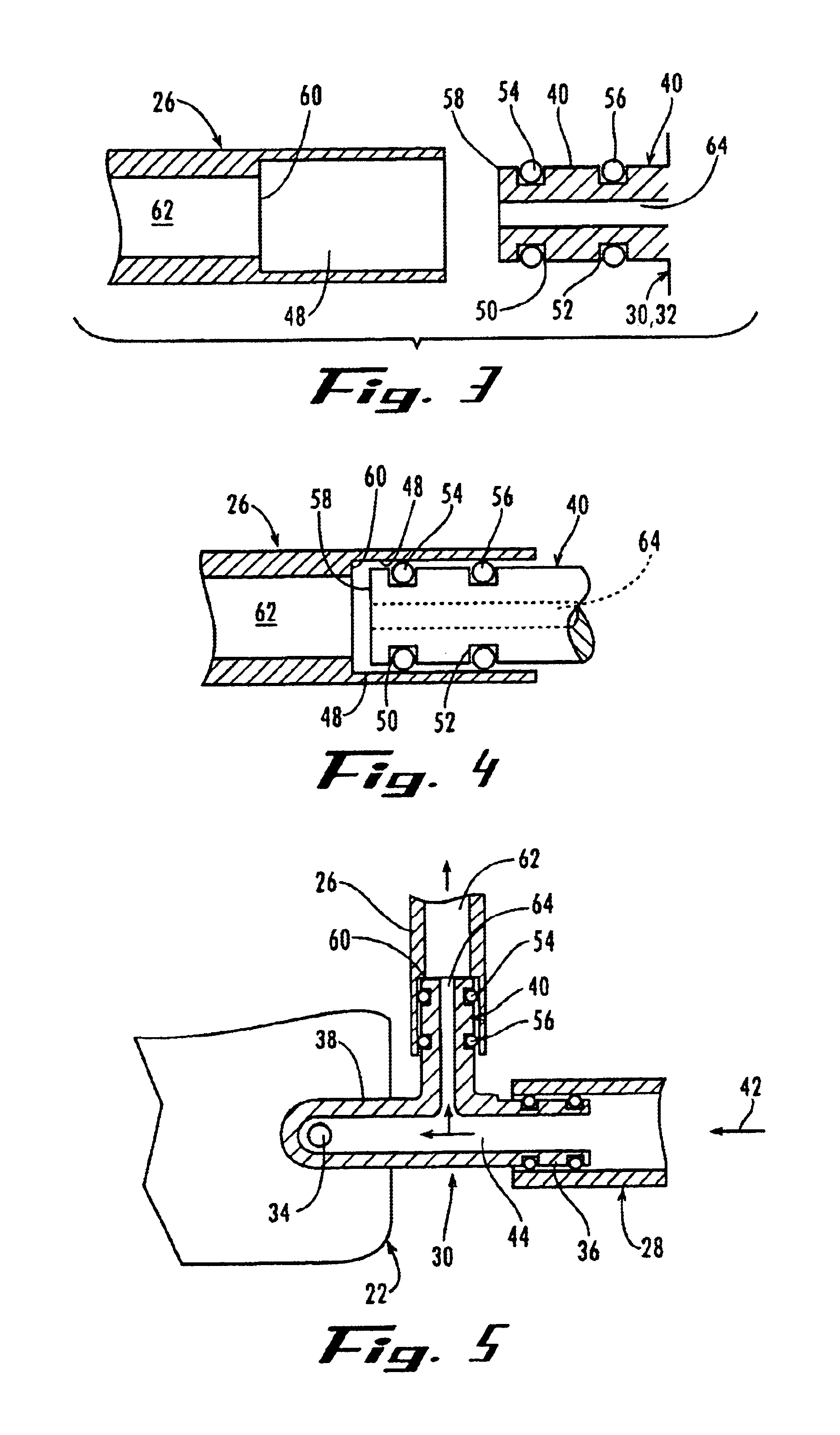
As shown in FIGS. 2 and 5, a fuel receiving fixture 30 or 32 is mounted to each fuel bowl 22, 24, respectively, and the fuel receiving fixture 30 communicates with the delivery end of the fuel line 28 that extends from the fuel pump 16 about the engine 10. A fuel inlet port of each fuel b...


PUM

PropertyMeasurementUnit
lengthaaaaaaaaaa
diameteraaaaaaaaaa
accelerationaaaaaaaaaa

Abstract

Fuel bowls are placed on opposite sides of a carburetor, and a fuel transfer tube extends between the fuel bowls. External fuel receiving fixtures are mounted in fluid communication with the fuel bowls and have nipples facing each other. The fuel transfer tube is telescopically mounted at its ends to the nipples and O-rings seal the ends of the tubes to the nipples.

Description

FIELD OF THE INVENTIONThis invention concerns the supply of fuel to a carburetor of an internal combustion engine. More particularly, the invention concerns the supply of fuel to the fuel bowls that straddle a carburetor, and the improved fuel transfer tube assembly that extends between the fuel bowls.BACKGROUND OF THE INVENTIONMany high performance internal combustion engines used for racecars employ carburetors for delivering fuel to the engines. Because a race car experiences extreme surges front to rear and side to side during its performance on the track, the fuel in the fuel bowl that supplies the fuel to the carburetor also tends to surge, so that the fuel in the fuel bowl sometimes tends to surge in the fuel bowl away from the carburetor. If the outlet port of the fuel bowl is adjacent the carburetor, there is a hazard of temporary starvation of fuel from the carburetor when the fuel surges away from the carburetor.One solution for the problem is to provide two fuel bowls th...

Claims


Application Information

Patent Timeline
Patent Type & Authority Patents(United States)
IPC IPC(8): F02M9/00F02B27/02F02M29/00F02M29/04F02M35/10
CPCF02M9/00F02M29/04F02M35/10144F02M35/10019Y10S261/50
Inventor GRANT, BARRY S.
Owner HOLLEY PERFORMANCE PRODUCTS
Why Eureka
Try Eureka