
Diaphragm carburetor with air purge system

a technology of air purge system and diaphragm carburetor, which is applied in the direction of liquid fuel feeder, machine/engine, separation process, etc., can solve the problems of difficult starting of engines fueled by them, air trapped, fatiguing operators, etc., and achieves the effect of improving the steady state operation of the engine and reducing the number of pull cord actuating strokes

Inactive Publication Date: 2005-04-05
WACKER NEUSON PRODN AMERICAS
View PDF20 Cites 11 Cited by
  • Summary
  • Abstract
  • Description
  • Claims
  • Application Information

AI Technical Summary

Benefits of technology

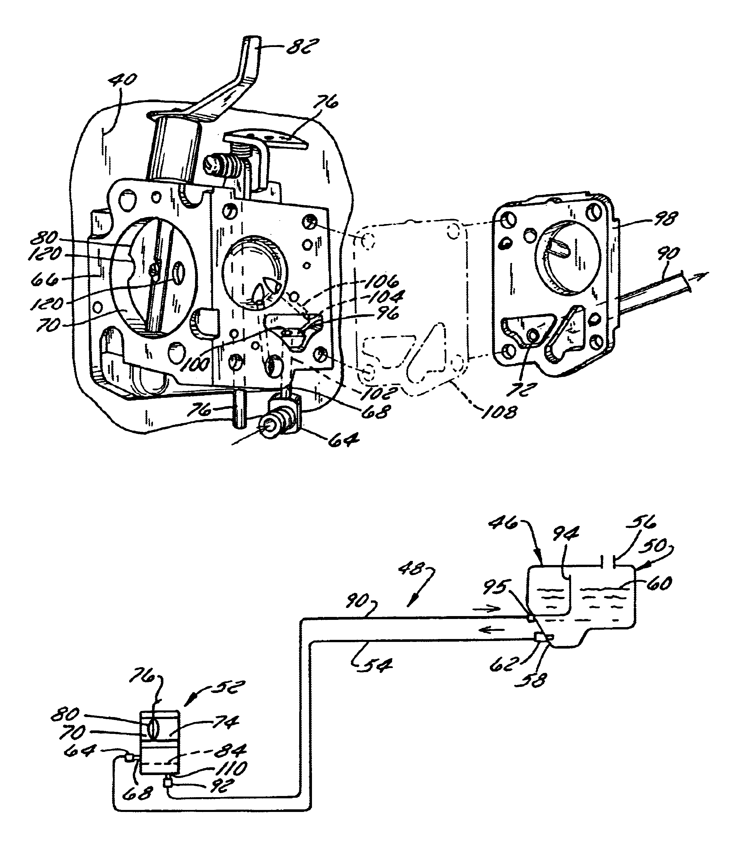
In accordance with a first aspect of the invention, the need identified above is satisfied by providing a fuel system with a vented diaphragm carburetor. Specifically, the engine's fuel supply passage opens into a vent passage that is configured to vent trapped vapor from the fuel supply passage. The fuel supply passage supplies fuel to a metering chamber of the carburetor from the fuel tank. It typically comprises 1) a fuel supply tube that supplies fuel to the fuel inlet of the carburetor from the fuel tank and 2) internal passage(s) supplying fuel to the metering chamber from the fuel inlet of the carburetor. The vent passage preferably comprises a vent tube having an inlet that opens into the fuel supply passage and having an outlet configured to open into an upper portion of the fuel tank. The vent tube inlet preferably opens into either an internal passage in the carburetor, such as into a pump diaphragm chamber of the internal passage, or a downstream portion of the fuel supply tube. The vent passage reduces the number of pull cord actuating strokes required to start a typical two-stroke or four-stroke engine after the engine has run out of fuel and has been refueled. This reduction is from at about 15 pull cord strokes to no more than 5, and even to 3 or less if the vent tube opens into an internal passage of the carburetor. It also can improve steady state operation of the engine by purging fuel vapor from a hot carburetor.
Another benefit of the inventive air purge system is that permits the use of a choke plate that is incapable of being fully closed. For instance, if the choke plate comprises a butterfly valve, the butterfly valve may have at least one aperture formed therethrough through which air passes when the butterfly valve is fully closed. An engine fueled with such a carburetor can start and idle with the choke fully set, hence negating the need to for the operator to detect a false hit and then back off the choke before starting the engine.
The air purge system may also reduce or avoid vapor lock by venting vaporized fuel from the fuel supply passage during engine operation.

Problems solved by technology

A relative disadvantage of diaphragm carburetors is that engines fueled by them can be difficult to start, particularly when the engine has run out of fuel.
This is because air can be trapped in the carburetor passage upstream of the diaphragm and in the fuel supply tube leading from the fuel tank to the carburetor.
This can be very fatiguing to operators.
Operation of a prime bulb may result in the injection of fuel into the throat of the carburetor.
Moreover, activation of a prime bulb when the engine is warm, or when the engine fails to start on the first attempt, can flood the engine so that the engine will not start.
Moreover, prime bulbs usually are made of rubber or another resilient material that may become brittle with age and with contact with fuel.
They therefore have a limited life.
This life is further limited by the imposition of shocks and vibrations on the engine during operation of some implements, such as rammers and breakers.
Closed chokes require even more complex operator interaction than is required for actuation of a prime bulb.
They also increase the risk of engine flooding.

Method used


Image

  • Diaphragm carburetor with air purge system
  • Diaphragm carburetor with air purge system
  • Diaphragm carburetor with air purge system

Examples


Embodiment Construction

1. System Overview

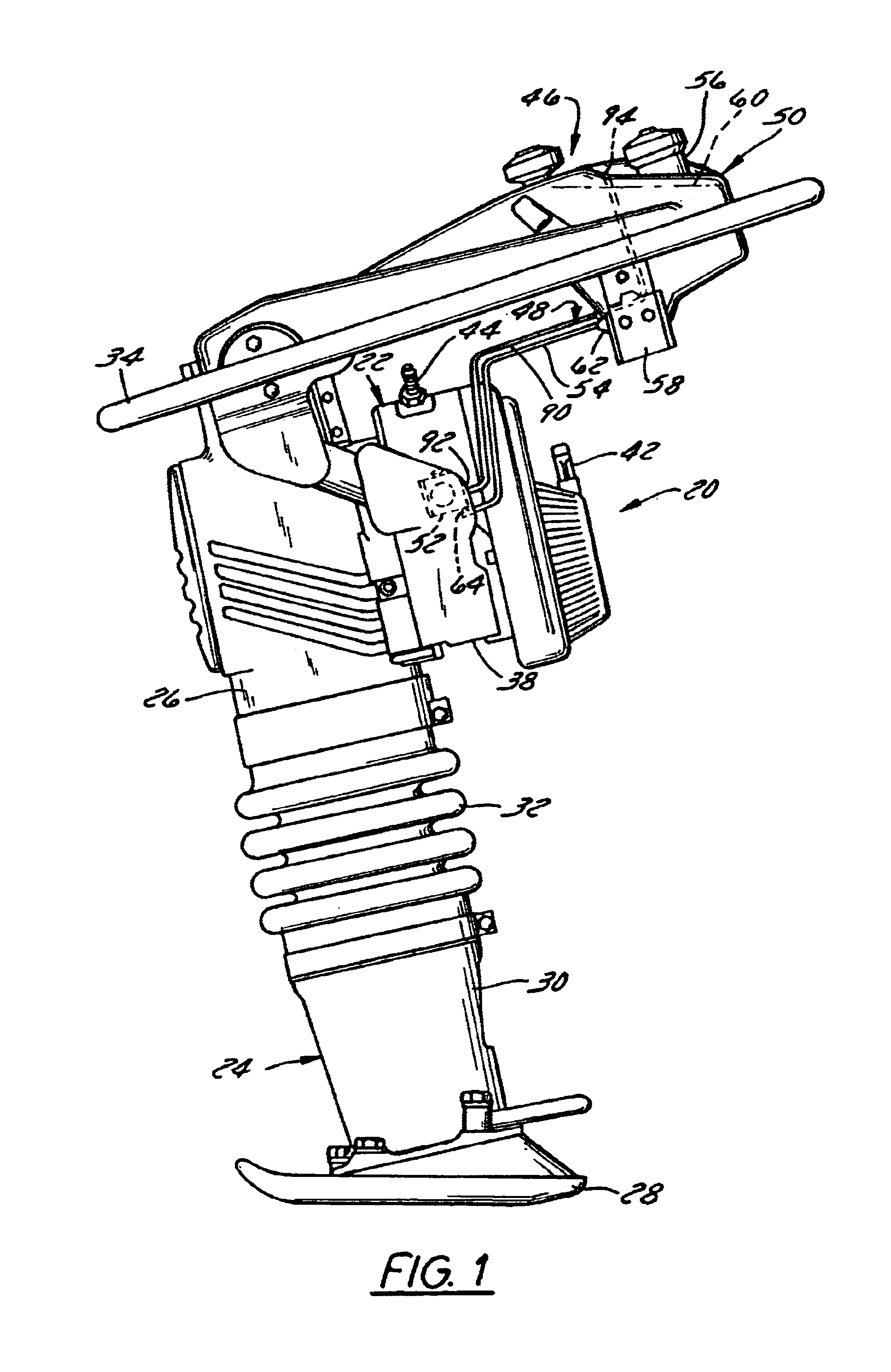
The inventive air purge system is usable with virtually any diaphragm carburetor-equipped two-stroke or four-stroke engine. Applications for these engines are also myriad. Hence, while a preferred embodiment of the inventive air purge system will now be described in conjunction with a reciprocating impact tool powered by such an engine, an engine, specifically a rammer, it is to be understood that it is usable with a variety of other powered devices as well.

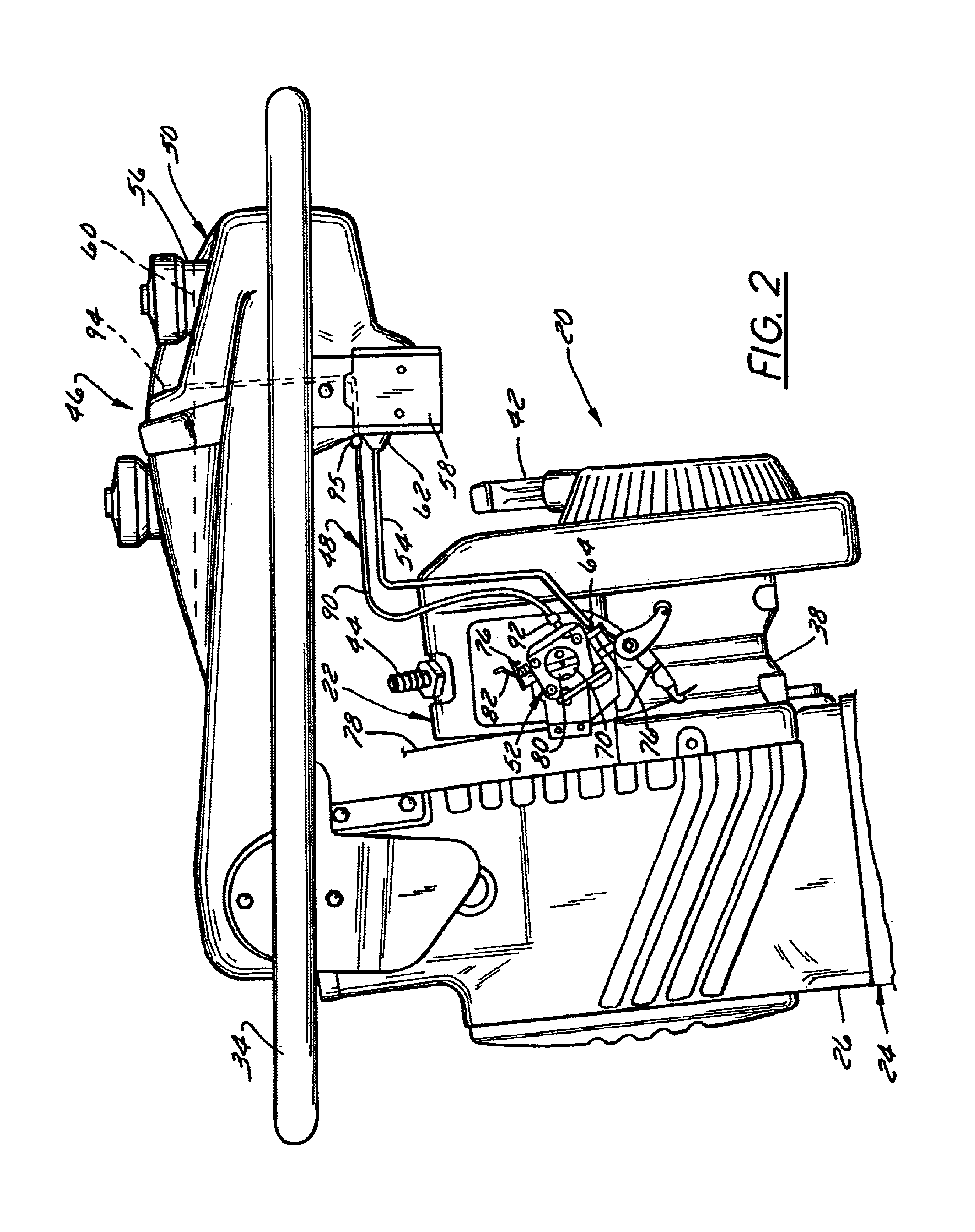
Referring now to the drawings and initially to FIGS. 1-3, a rammer (sometimes known as a tamper) 20 is illustrated that includes an engine 22 and a rammer subassembly 24 bolted to one another to form an integral unit. The rammer subassembly 24 includes a rammer crankcase 26 and a reciprocating tamping shoe 28 connected to the rammer crankcase 26 by a reciprocating piston (not shown) so as to oscillate or reciprocate vertically upon rammer operation. The piston is protected at its lower end by a fixed guard 30 an...


PUM

PropertyMeasurementUnit
surface areaaaaaaaaaaa
vacuumaaaaaaaaaa
gravityaaaaaaaaaa

Abstract

A diaphragm carburetor-based fuel supply system is equipped with an air purge system that vents trapped air from the fuel supply system. The air purge system preferably includes a vent tube having an outlet opening into the upper portion of the system's fuel tank and an inlet located as close as practical to the diaphragm chamber of the carburetor, preferably within an internal passage of the carburetor or at least in a fitting or fuel supply tube portion located closely adjacent the fuel inlet of the carburetor. The resulting system requires only a few pull strokes to start a freshly fueled engine, as opposed to about 15 strokes in a system lacking such an air purge system. It also permits the use of a choke that is incapable of fully closing, thereby negating the need for a “false hit” during cold engine start.

Description

BACKGROUND OF THE INVENTION1. Field of the InventionThe invention relates to fueling systems and, more particularly, relates to a fueling system utilizing a diaphragm carburetor to form an air / fuel mixture and to supply the mixture to an engine. The invention additionally relates to an engine fueled with such a system and a method of its use.2. Discussion of the Related ArtDiaphragm carburetors are widely used to supply fuel to relatively small two-stroke and four-stroke utility engines. A diaphragm carburetor has a diaphragm chamber which opens to main jet and idling jet orifices. Fuel flow through the carburetor is controlled by a regulator located in the diaphragm chamber. The regulator continually opens and closes an inlet needle in response to the vacuum created in the carburetor's venturi. Fuel is supplied to the inlet needle via either a diaphragm pump or by gravity. In the case of the diaphragm pump, suction pulses of the engine are used force fuel through the pump and a ser...

Claims


Application Information

Patent Timeline
Patent Type & Authority Patents(United States)
IPC IPC(8): F02M17/00F02M17/04F02M1/02F02M37/06
CPCF02M17/04
Inventor LAHNER, WILLIAMORZAL, GREGORY
Owner WACKER NEUSON PRODN AMERICAS
Learn More