
Radial piston pump for producing high fuel pressure, as well as method for operating an internal combustion engine, computer program, and control and/or regulating unit

a technology of high fuel pressure and radial piston, which is applied in the direction of machines/engines, electric control, positive displacement liquid engines, etc., can solve the problem of correspondingly low torque on the drive shaft, and achieve the effect of more simple and inexpensive production

Inactive Publication Date: 2005-03-29
ROBERT BOSCH GMBH
View PDF11 Cites 9 Cited by
  • Summary
  • Abstract
  • Description
  • Claims
  • Application Information

AI Technical Summary

Benefits of technology

The object of the current invention is to modify a radial piston pump of the type mentioned above so that the fuel system in which it is used can be more simply and inexpensively produced.
An advantageous modification to this proposes that before the starting of the engine, the adjusting ring be moved against a mechanical stop, which defines an angular position of the adjusting ring in relation to the drive shaft in which the stroke ring is at least essentially approximately coaxial to the rotation axis of the drive shaft, and that a balancing of the control electronics be executed in this position. This modification of the method according to the invention has the advantage that before each start of the engine, the control electronics can be adjusted to the zero position of the adjusting ring precisely predetermined by the mechanical stop. This increases the precision in the adjustment of the adjusting ring and consequently increases the precision in the adjustment of the fuel quantity delivered by the radial piston pump.

Problems solved by technology

In addition, when only a small fuel quantity is to be delivered by the radial piston pump, only a correspondingly low torque on the drive shaft is required.

Method used


Image

  • Radial piston pump for producing high fuel pressure, as well as method for operating an internal combustion engine, computer program, and control and/or regulating unit
  • Radial piston pump for producing high fuel pressure, as well as method for operating an internal combustion engine, computer program, and control and/or regulating unit
  • Radial piston pump for producing high fuel pressure, as well as method for operating an internal combustion engine, computer program, and control and/or regulating unit

Examples


Embodiment Construction

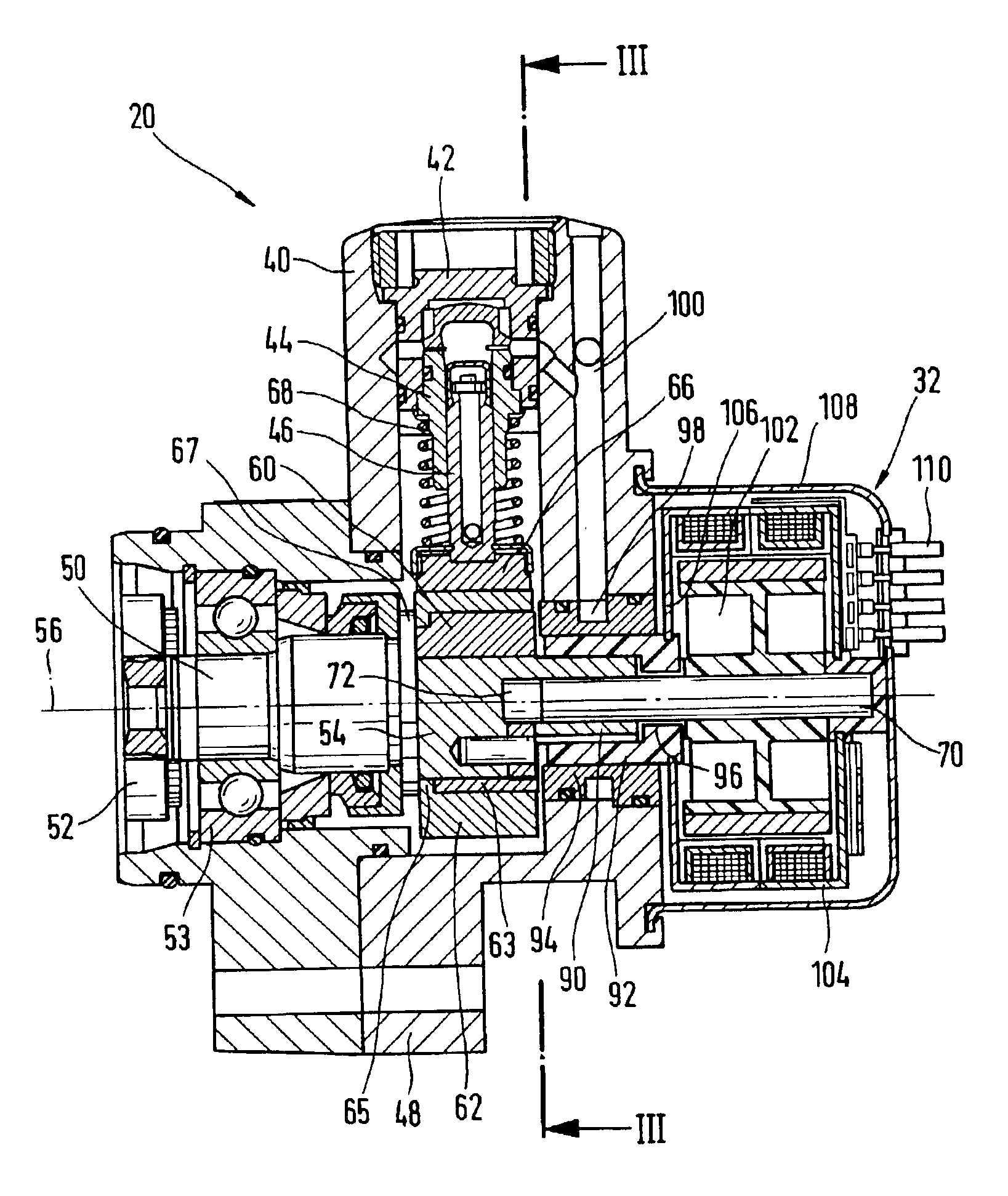
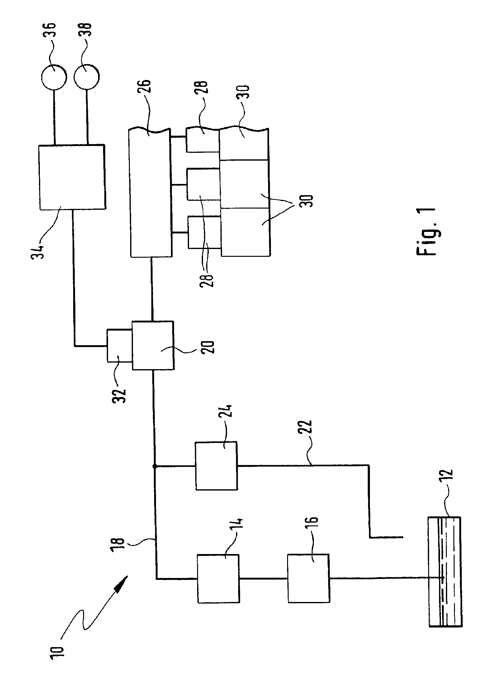
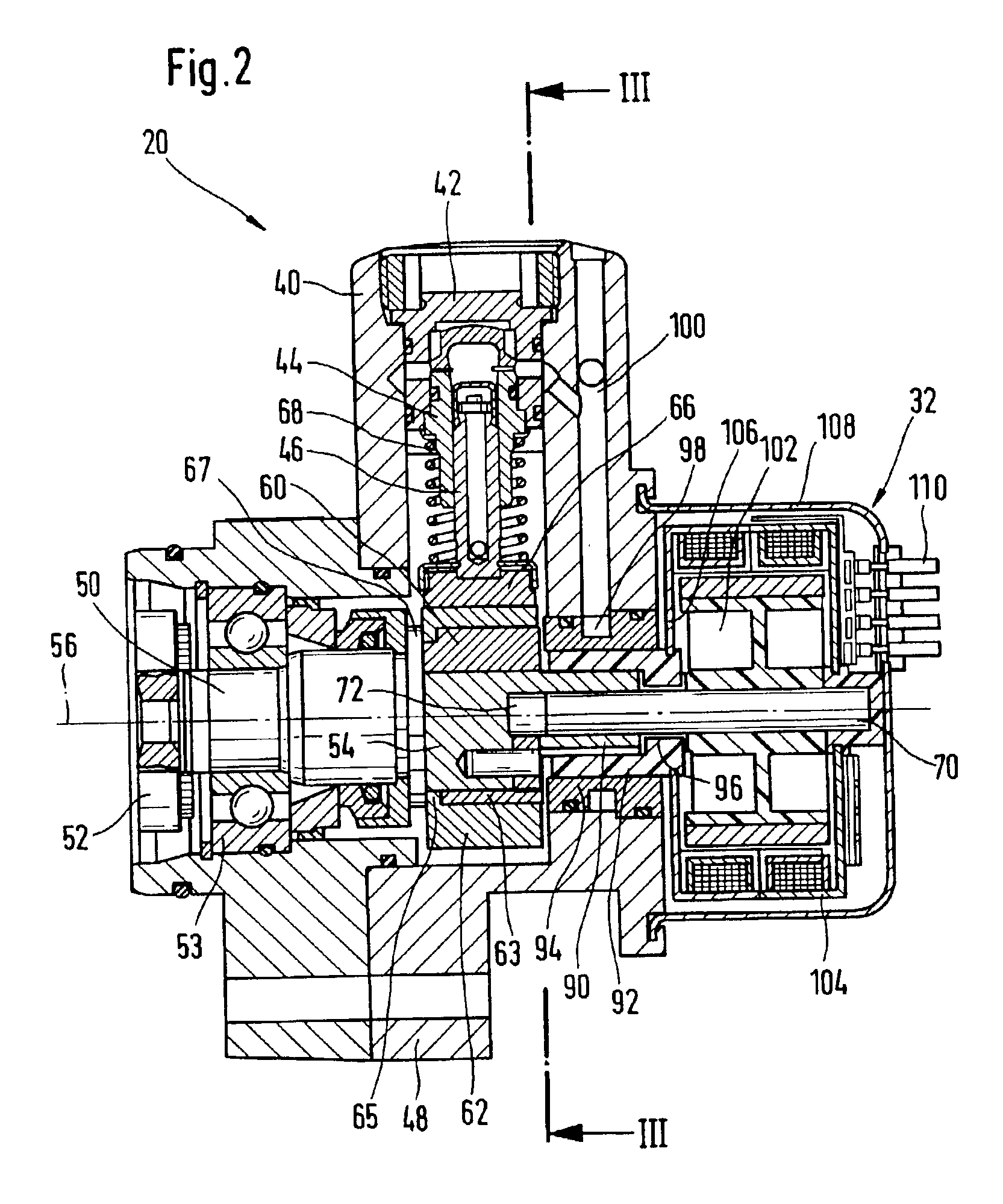
In FIG. 1, a fuel system is labeled with the reference numeral 10. It includes a fuel tank 12 from which an electric fuel pump 14 delivers fuel by means of a filter 16. A low-pressure fuel line 18 connects the electric fuel pump 14 to a high-pressure fuel pump 20. A branch line 22, which contains a pressure regulating valve 24, branches from the low-pressure fuel line 18, between the electric fuel pump 14 and the high-pressure pump 20.

The high-pressure fuel pump 20 delivers the fuel into a fuel accumulation line 26, in which the fuel is stored under very high-pressure. The accumulation line 26 is connected to a number of injectors 28, which inject the fuel directly into combustion chambers 30.

As will be explained in detail further below, the fuel quantity delivered by the high-pressure fuel pump 20 to the fuel accumulation line 26 can be changed. To this end, the high-pressure fuel pump 20 includes an electric motor 32, which is activated by a control and / or regulating unit 34. This...


PUM


Abstract

A radial piston pump used for producing high fuel pressure in fuel systems of internal combustion engines, in particular in a common rail injection system includes a housing with at least one cylinder and a drive shaft is supported in the housing and having at least one cam section. A stroke ring is disposed encompassing the cam section a piston contained in each cylinder is supported against the stroke ring. A possibility for adjusting the delivery quantity of the radial piston pump is achieved in that an adjusting ring is disposed between the cam section and the stroke ring and the internal opening of this adjusting ring is eccentric in relation to the outer contour and can be rotated around the central axis of the internal opening into a desired angular position in relation to the cam section.

Description

BACKGROUND OF THE INVENTION1. Field of the InventionThe invention relates first to a radial piston pump for producing high fuel pressure in fuel systems of internal combustion engines, in particular in a common rail injection system, with a housing that has at least one cylinder, with a drive shaft that is supported in the housing and has at least one cam section, with a stroke ring that is disposed encompassing the cam section, and with at least one piston that is contained in the cylinder and is supported against the stroke ring.2. Description of the Prior ArtA radial piston pump of the type with which this invention is concerned is known from DE 198 58 862 A1. In it, three cylinders are arranged in the form of a star around a cam section of a central drive shaft. A stroke ring is placed onto the cam section and is connected to the radially inner ends of the pistons contained in the cylinders. The stroke ring itself does not rotate, but moves along a circular path in its plane. Th...

Claims


Application Information

Patent Timeline
IPC IPC(8): F04B49/12F04B1/04F04B1/00F02M59/10F02D41/04F02D41/40F02M59/06F02M59/20F02M59/30
CPCF04B49/126F04B1/0404F04B1/07
Inventor STIEFEL, HANS-PETER
Owner ROBERT BOSCH GMBH
Learn More