
Suction-attached support device and method

a support device and suction device technology, applied in the field of vacuum suction device and method, can solve the problems of installation difficulty, inability to properly position the construction piece, etc., and achieve the effect of quick and easy positioning of the construction pi

Inactive Publication Date: 2005-03-29
ANTILL KEITH R
View PDF21 Cites 4 Cited by
  • Summary
  • Abstract
  • Description
  • Claims
  • Application Information

AI Technical Summary

Benefits of technology

The step of positioning the support device may be accomplished by extending an elongate spacer member from the support device to an extended position, and abutting the spacer member against a previously installed siding or trim piece or other fixed part of the building. Additionally or alternatively, the step of positioning the support device may include positioning the support device abutting an existing surface, and the method may then include the steps of inserting an end of a tape measure into a notch in the support device, extending the tape measure to measure how long the siding or trim piece needs to be, and shortening the siding or trim piece to the measured length.
In view of the foregoing, it will be appreciated that the present invention provides a way for one person to install siding, trim, and / or other construction pieces by himself without the assistance of a helper. In particular, the invention includes devices and methods enabling one person to quickly and easily position the construction piece in place on the building, hold the construction piece in place, and permanently nail it there.

Problems solved by technology

Siding, trim, and other construction pieces are usually too long, cumbersome, and heavy for one person to properly position on a building, hold there in place, and nail or otherwise permanently affix to the building.
But sometimes a helper is not available or is too costly, and then the installer can not do the job by himself.
This results in delays and / or increased costs in constructing or maintaining the building.

Method used


Image

  • Suction-attached support device and method
  • Suction-attached support device and method
  • Suction-attached support device and method

Examples


Embodiment Construction

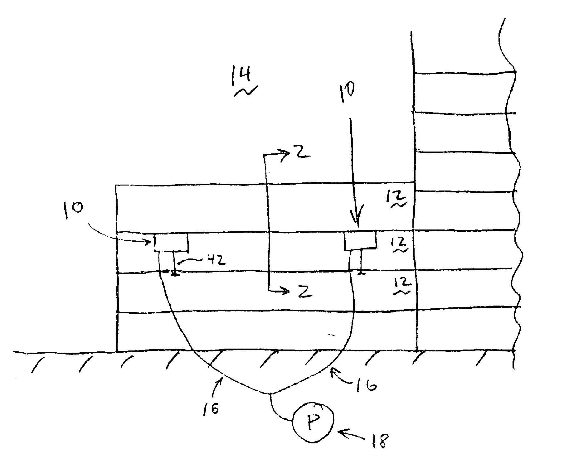
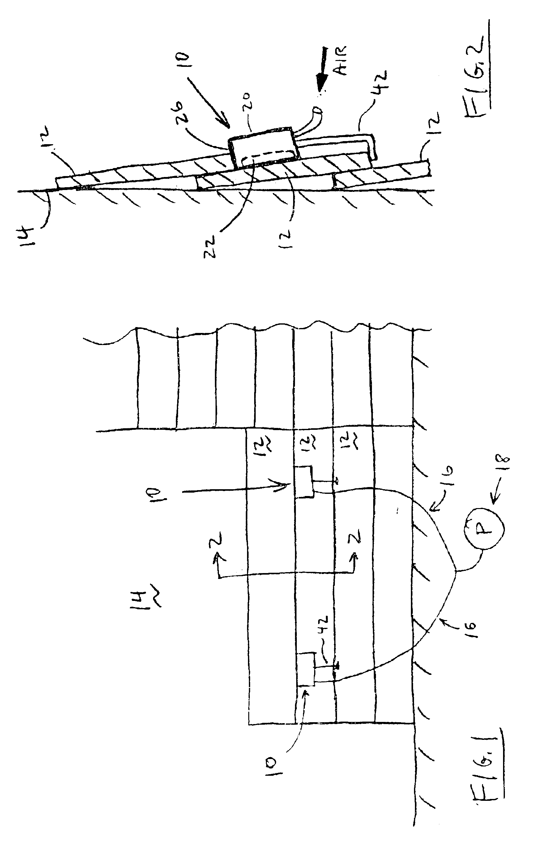
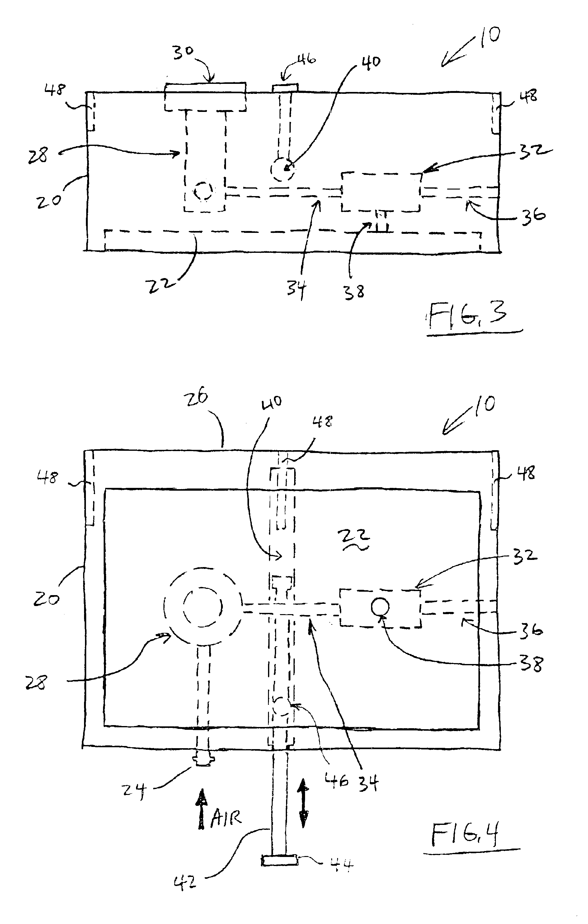
Referring now to FIGS. 1-4, a first exemplary embodiment of the present invention provides a suction-attached support device 10, referred to generally as the device 10. As shown in FIGS. 1 and 2, the device 10 is used for installing construction pieces 12 on a building structure wall 14. The device 10 can be used to install construction pieces 12 such as siding, trim, or other items. The device 10 is connected by fluid lines 16 such as hoses to a suction-inducing device 18 such as a compressor, vacuum pump, or other device. The suction-inducing device 18 can operate using air or another fluid. It will be understood that the device 10 described herein is only one exemplary embodiment of the invention, and that those skilled in the art will recognize that the device can be adapted for use in other applications not expressly described herein but still included in the invention.

As shown in FIGS. 3 and 4, the device 10 includes a body 20, a suction cup 22 attached to the body, and a flui...


PUM


Abstract

A body has a support surface for temporarily supporting a siding, trim, or other construction piece that is to be installed on a building wall. A suction cup is controllable to temporarily adhere by suction the support device to the building wall. An extendible spacer is used to accurately position the support device on the building wall. Notches in the body receive the ends of a tape measure or chalk line for accurately sizing and positioning the construction pieces. The support device can be used with existing compressors, vacuum pumps, or other suction-inducing devices. A venturi tube in the body generates the suction when an air compressor is used. A method of installing the siding, trim, or other construction pieces is also provided.

Description

TECHNICAL FIELDThe present invention relates to building construction and maintenance devices and methods and, more particularly, to vacuum-suctioning devices and methods for installing siding, trim, and / or other construction pieces.BACKGROUND OF THE INVENTIONSiding, trim, and other construction pieces are usually too long, cumbersome, and heavy for one person to properly position on a building, hold there in place, and nail or otherwise permanently affix to the building. Typically, these types of jobs require at least two people, an installer to do the nailing and a helper to help position and hold the siding piece in place. But sometimes a helper is not available or is too costly, and then the installer can not do the job by himself. This results in delays and / or increased costs in constructing or maintaining the building.Accordingly, what is needed but not found in the prior art is a way for one person to install siding, trim, and / or other construction pieces by himself without t...

Claims


Application Information

Patent Timeline
IPC IPC(8): E04F21/18
CPCE04F21/1855Y10S269/904Y10S33/02
Inventor ANTILL, KEITH R.
Owner ANTILL KEITH R
Learn More