
Pipe joining tool

a pipe and tool technology, applied in the direction of manufacturing tools, soldering devices, auxillary welding devices, etc., can solve the problems of high labor intensity, high labor intensity, and difficulty in welding fittings onto pipes, so as to reduce the likelihood of accidents, reduce labor intensity, and quickly and easily position

Active Publication Date: 2006-01-31
SHELTON WILLIAM C
View PDF13 Cites 5 Cited by
  • Summary
  • Abstract
  • Description
  • Claims
  • Application Information

AI Technical Summary

Benefits of technology

Enables solo operation, reduces accident risk, lowers costs, and simplifies the welding process by allowing quick and safe alignment of pipe fittings, reducing the need for extensive training and manpower.

Problems solved by technology

Welding fittings onto pipe is a difficult undertaking, often requiring a pair of men to perform satisfactorily.
This is hazardous work where burns, bruises, strains and broken bones are not uncommon.
Of course, the work is costly because the men performing it must be highly skilled and well-paid.
Additionally, both of these men must be covered by expensive insurance to offer them some protection in the event of an accident.

Method used


Image

  • Pipe joining tool
  • Pipe joining tool
  • Pipe joining tool

Examples


Embodiment Construction

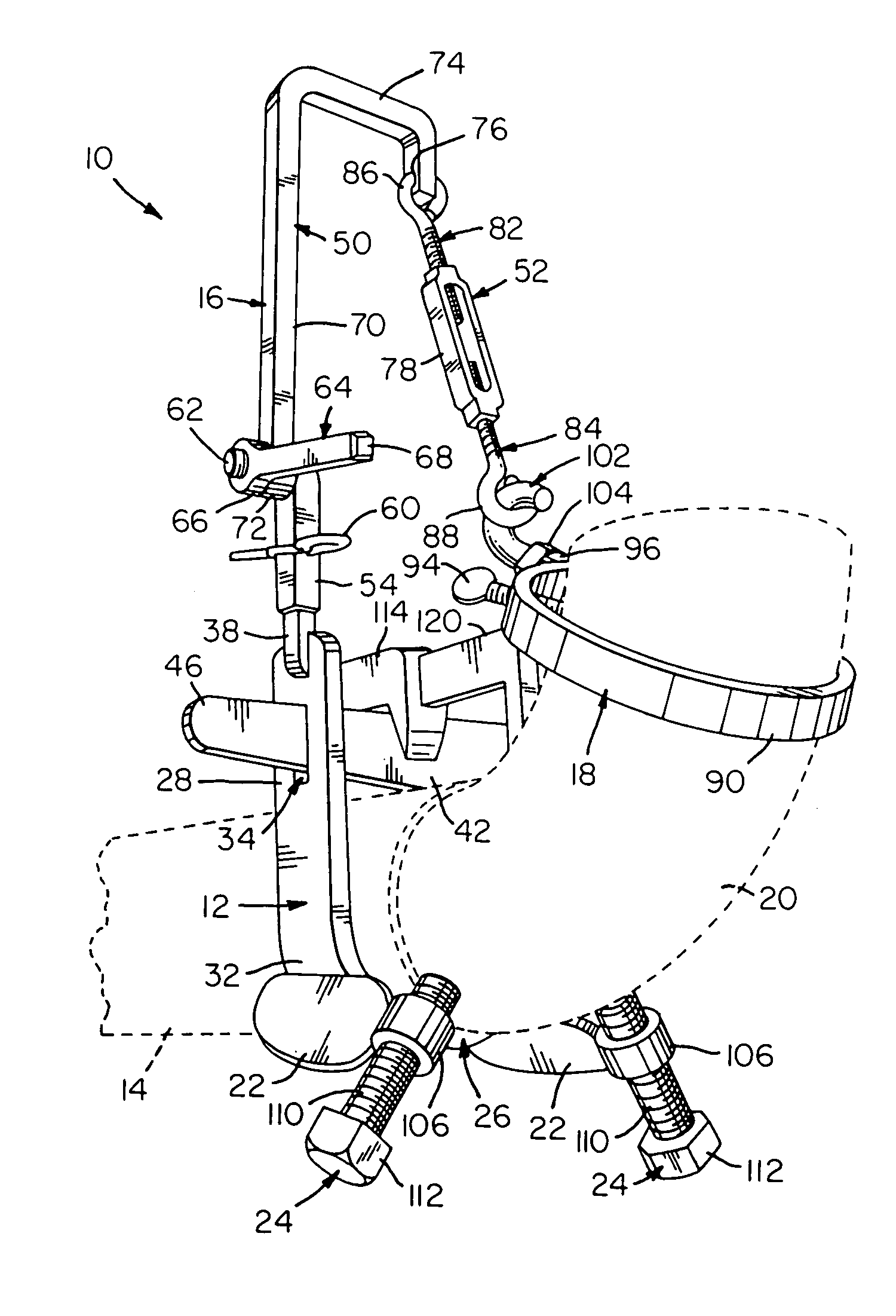
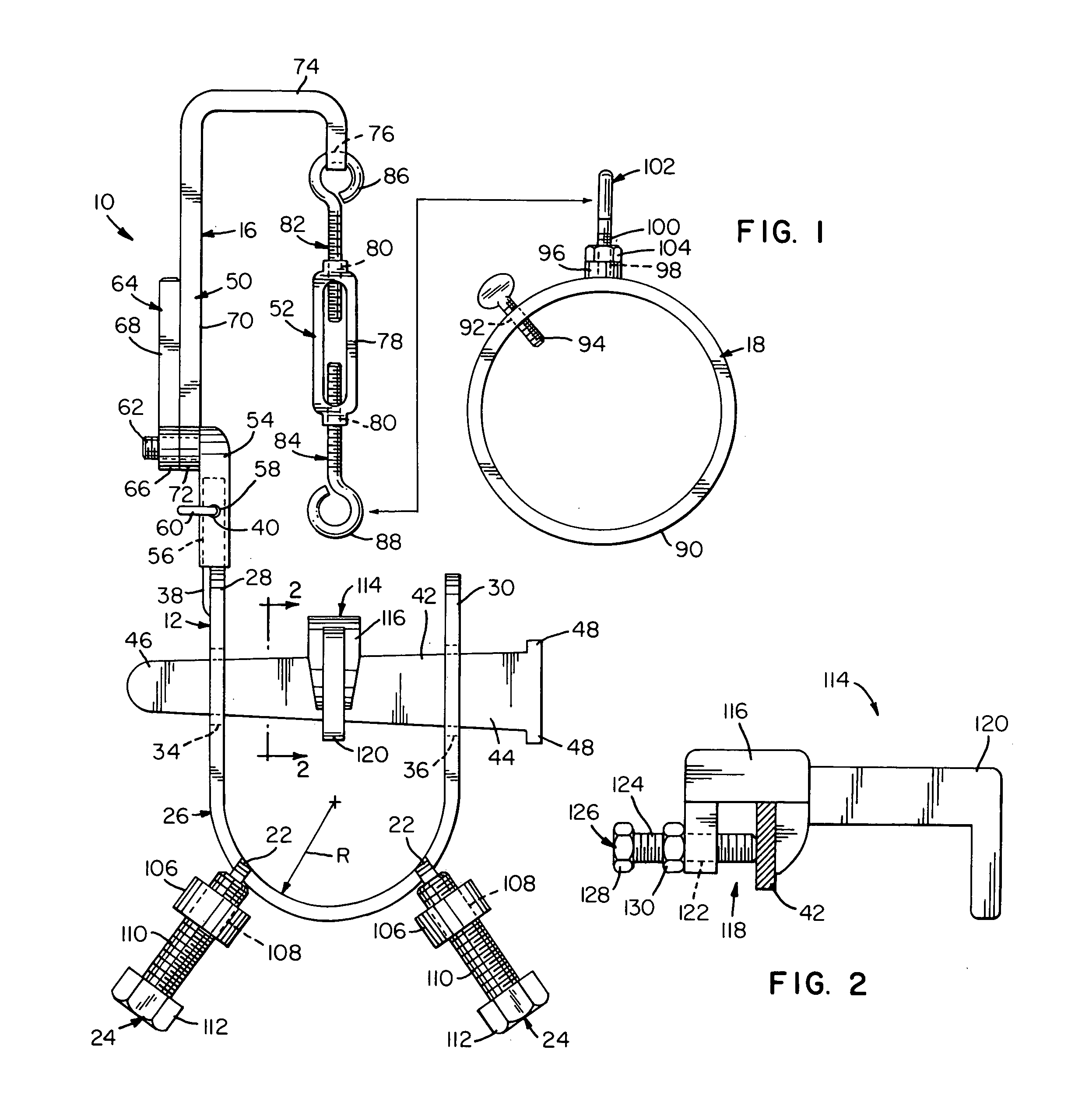
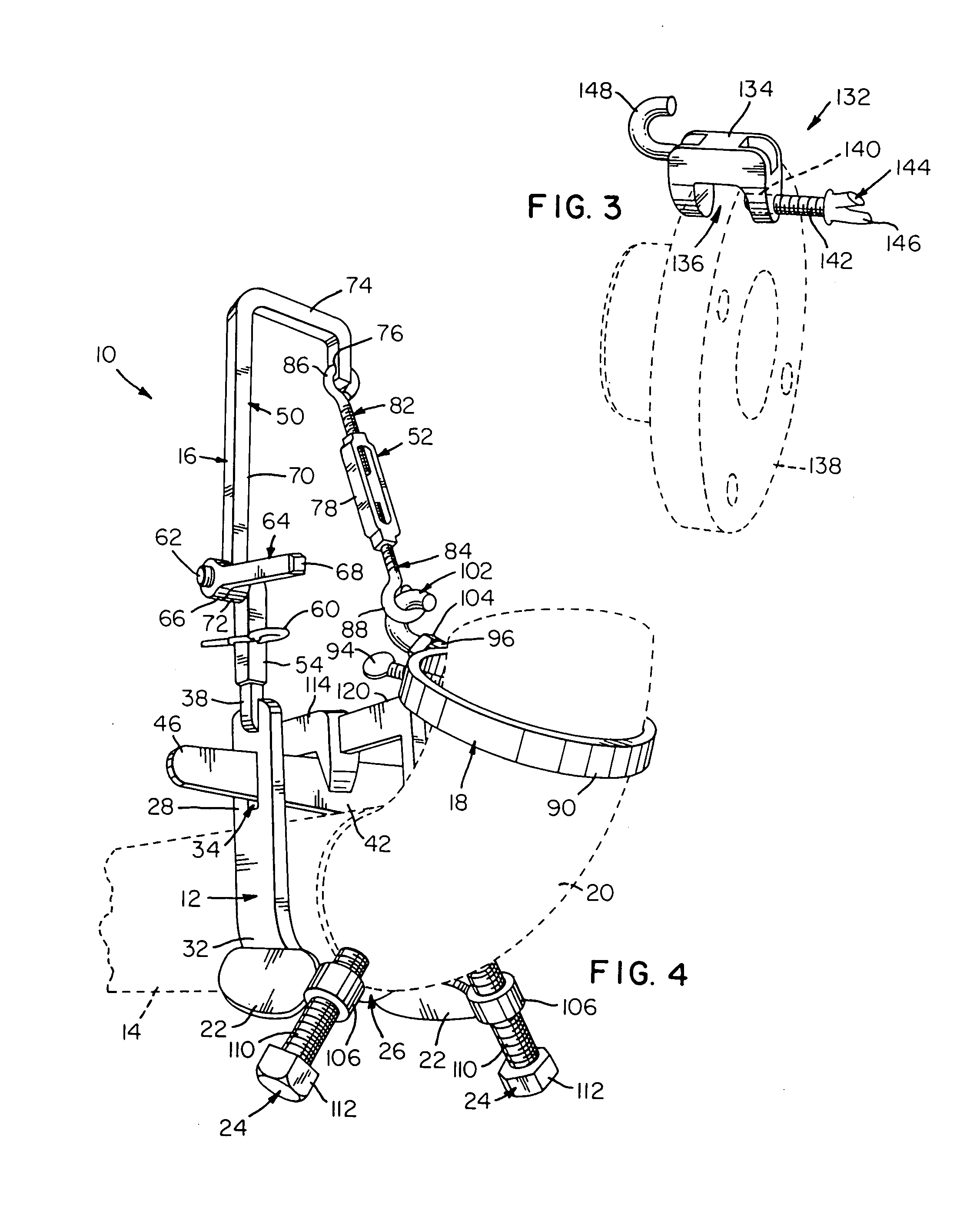
[0018]Referring now to the FIGS., a pipe joining tool in accordance with the present invention is shown at 10. Tool 10 includes a mounting bracket 12 adapted for releasable attachment to one end of a pipe 14. A flexible link 16 is secured to mounting bracket 12. Carried at the free end of flexible link 16 is a pipe fitting keeper 18 for releasably grasping a pipe fitting, such as ell 20, and suspending pipe fitting 20 adjacent the end of pipe 14. A pair of legs 22 projects from the bottom of mounting bracket 12 and carries a pair of bolts 24 that can help position pipe fitting 20 suspended by keeper 18 in alignment with pipe 14 so that pipe 14 and pipe fitting 20 can be welded together.

[0019]Mounting bracket 12 includes a U-shaped platform 26 having a pair of linear end portions 28 and 30 joined together by an arcuate intermediate portion 32. As shown, intermediate portion 32 is provided with a radius of curvature R that closely matches the external radius of pipe 14. End portions 2...


PUM

PropertyMeasurementUnit
diametersaaaaaaaaaa
diametersaaaaaaaaaa
flexibleaaaaaaaaaa

Abstract

A pipe joining tool including a mounting bracket for releasable attachment to a pipe. The mounting bracket has a U-shaped platform with an intermediate portion for engaging a pipe and a pair of slotted end portions extending from the opposite ends of the intermediate portion in a substantially parallel manner. A wedge slidably extends through the slots in the end portions for driving a pipe positioned within the U-shaped platform into tight engagement with the intermediate portion. A flexible link is secured to the mounting bracket and extends therefrom. A pipe fitting keeper is carried by the flexible link for releasably grasping a pipe fitting and suspending the pipe fitting adjacent the end of a pipe positioned within the U-shaped platform. A pair of spaced apart legs projects forwardly from the intermediate portion of the U-shaped platform. Each of the spaced apart legs has an internally threaded bore within which is positioned a bolt. Selective rotation of each bolt moves the pipe fitting suspended by the pipe fitting keeper into alignment with the end of a pipe positioned within the U-shaped platform.

Description

FIELD OF THE INVENTION[0001]The present invention relates generally to metal working apparatus and, more particularly, to means for assembling or disassembling.BACKGROUND OF THE INVENTION[0002]Welding fittings onto pipe is a difficult undertaking, often requiring a pair of men to perform satisfactorily. It is not unusual for one man to orient, align and support fittings, such as tees, ells and flanges, against the pipe ends while the other man welds them together. This is hazardous work where burns, bruises, strains and broken bones are not uncommon. Of course, the work is costly because the men performing it must be highly skilled and well-paid.[0003]Additionally, both of these men must be covered by expensive insurance to offer them some protection in the event of an accident.SUMMARY OF THE INVENTION[0004]In light of the problems associated with the known methods and apparatus for welding pipe fittings onto pipe, it is a principal object of the invention to provide the tool that p...

Claims


Application Information

Patent Timeline
Patent Type & Authority Patents(United States)
IPC IPC(8): B23P19/04B23K37/053B25B27/14
CPCB23K37/0533B23K37/0536Y10T29/5367Y10T29/53987Y10T29/53917
Inventor SHELTON, WILLIAM C.
Owner SHELTON WILLIAM C
Learn More