
Elevator system with one or more cars moving independently in a same shaft

a technology of elevator system and elevator shaft, which is applied in the direction of elevator, building lift, transportation and packaging, etc., can solve the problems of system not being able to move independently, system may still get out of order, exact collision risk, etc., and achieve reliable and well-functioning

Inactive Publication Date: 2005-03-29
KONE CORP
View PDF17 Cites 64 Cited by
  • Summary
  • Abstract
  • Description
  • Claims
  • Application Information

AI Technical Summary

Benefits of technology

The object of the present invention is to eliminate the above-mentioned drawbacks and to achieve an economical, reliable and well-functioning elevator system for tall buildings, said elevator system comprising one or more elevator cars moving in the same shaft independently of each other.
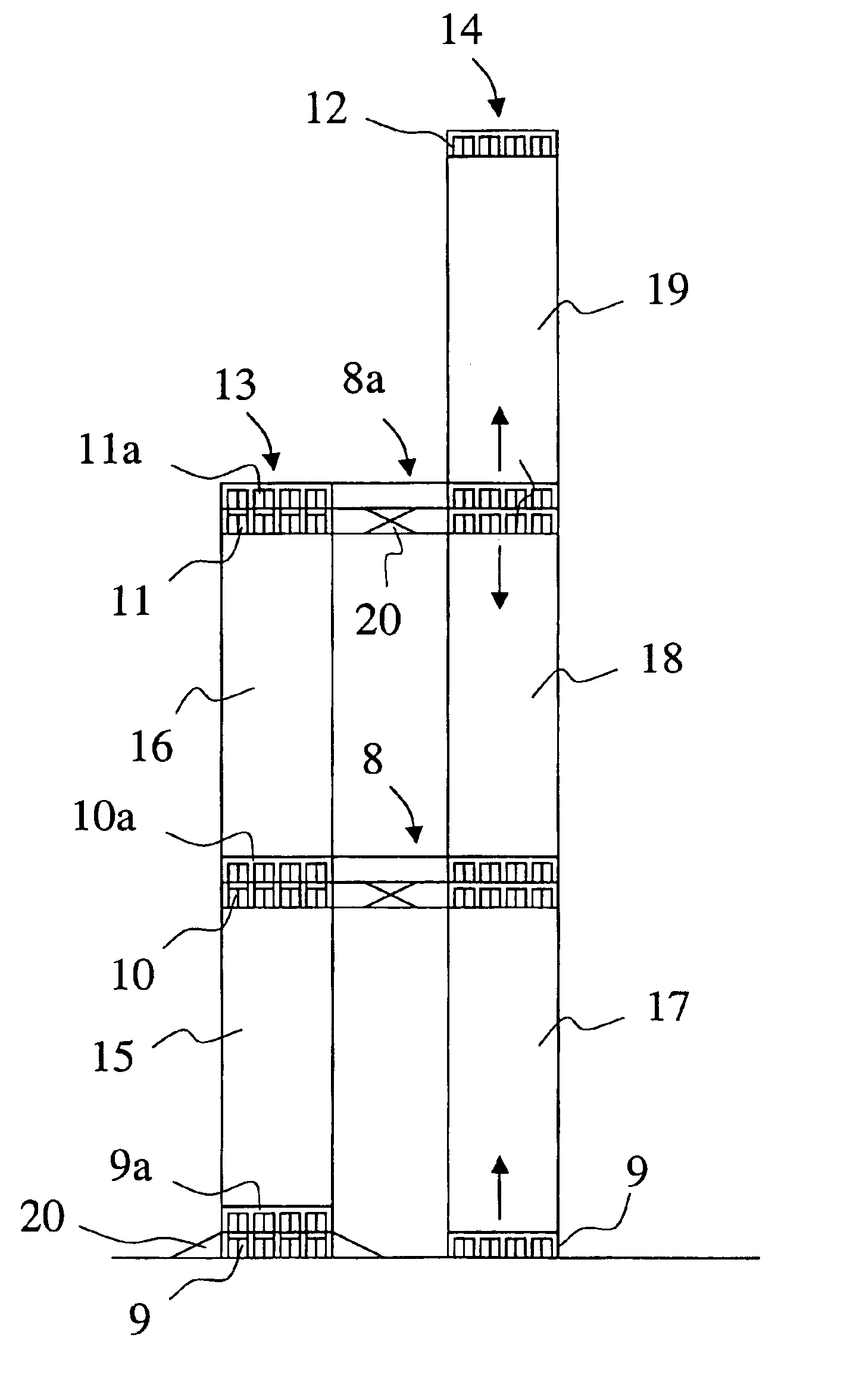
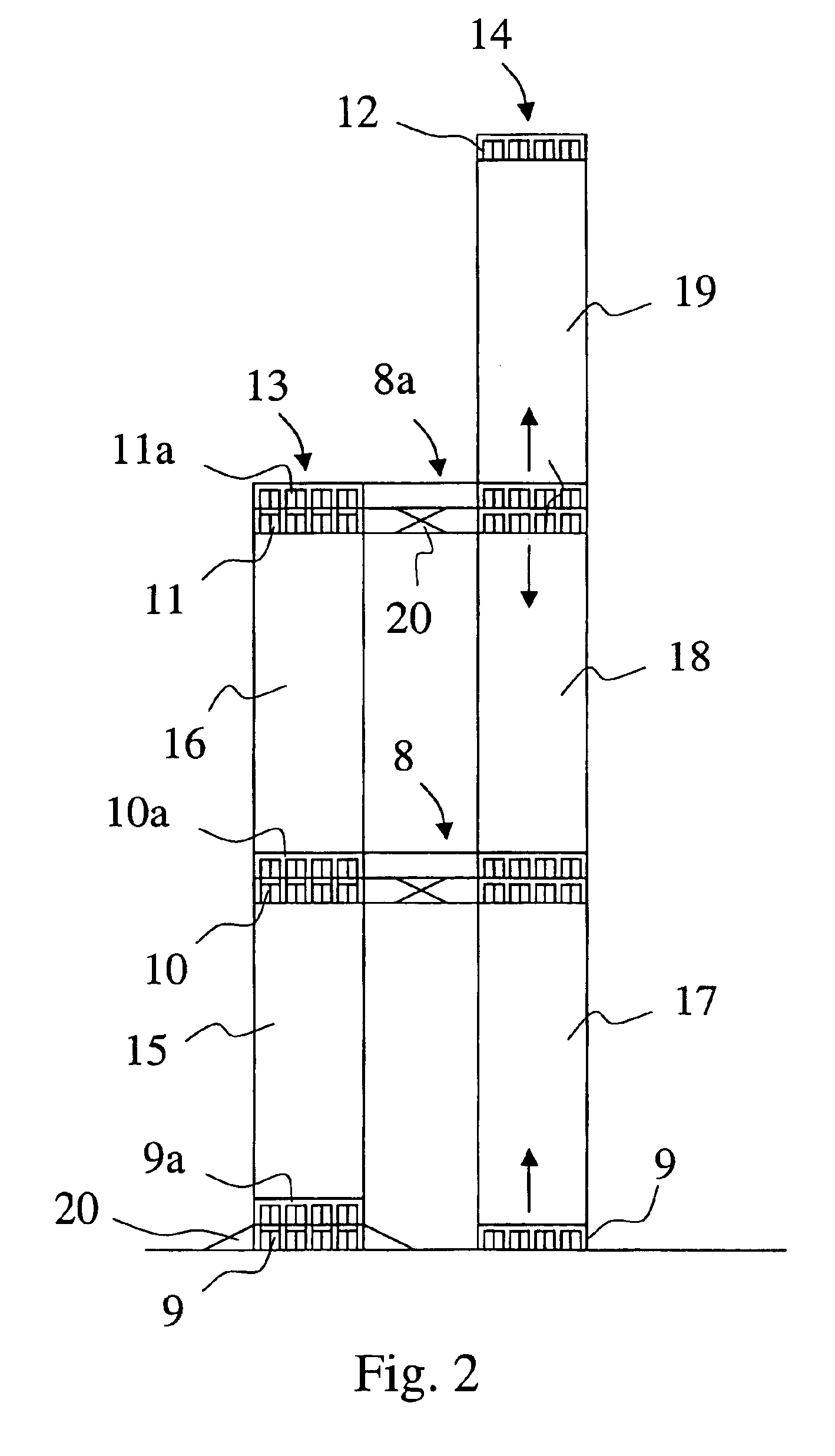
The solution of the invention has the advantage that by using simple solutions a reliable and safe elevator system is achieved that guarantees a good transport capacity in tall buildings and enables space savings to be made in respect of expensive floor area. According to the invention, for an elevator system in a building of the same height, elevator shafts are only needed for two elevator groups instead of three and yet at least the same capacity is achieved as in prior-art solutions. The greatest space saving is gained by leaving out the above-mentioned lowest zone, the so-called low-rise zone as separate elevator shafts, so that the entire shaft and lobby spaces for this zone, i.e. e.g. floors 1-15, can be used for other purposes. In the case of an elevator group of eight elevators, the additional area thus provided will be about 150 m2 for each floor. As the fifteen lowest floors can well be used as business premises, the rent per square meter of area of such floor space is generally high and therefore the elevator system of the invention allows the owner of the building to earn a good income from rents. An additional advantage is that, although the elevator cars travel in the same shaft independently of each other, they never collide because the hoisting ropes of different elevator cars are not interlapped in the vertical direction and there is therefore no risk of the elevator cars getting into each other's range of movement.

Problems solved by technology

The proposed elevator system is very complicated and it is obvious that such a system involves the problem of how to construct a sufficiently simple and safe control system.
Even if the control system were ever so safe, the system may still get out of order, in which case a collision between two cars is possible.
If a risk of collision appears, one of the elevator cars is moved away to give way to the other one.
The problem in this case, too, is exactly a risk of collision, because there is always the possibility that, if a program malfunction or error occurs, two elevator cars running towards each other in the same shaft will collide.

Method used


Image

  • Elevator system with one or more cars moving independently in a same shaft
  • Elevator system with one or more cars moving independently in a same shaft
  • Elevator system with one or more cars moving independently in a same shaft

Examples


Embodiment Construction

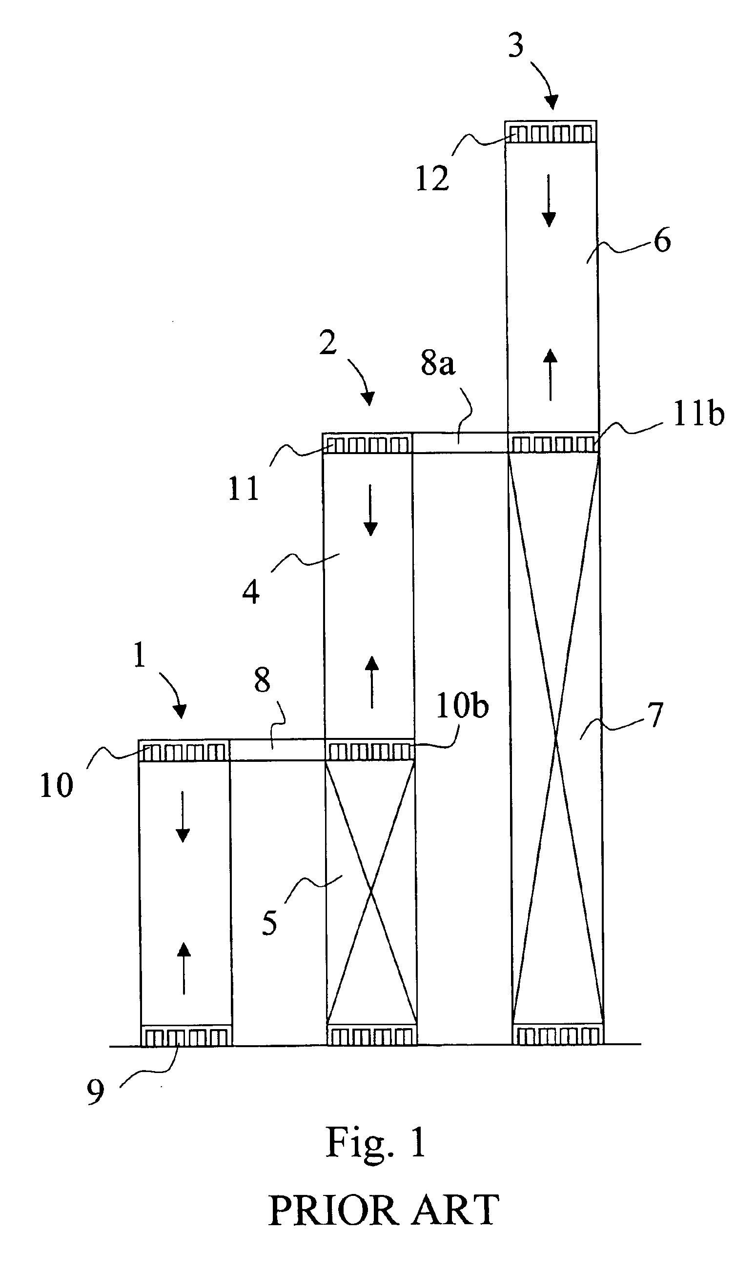
The solution illustrated in FIG. 1 represents the aforesaid prior-art elevator system for tall buildings. Let us consider e.g. a 45-floor building with fifteen floors in each zone. The number of floors in each zone is determined by the number of elevators and the car size and speed of the elevators. The system comprises three different height zones, so it requires three different banks of elevator shafts 1, 2 and 3, of which bank 1 forms the lowest zone, which comprises e.g. a group of eight elevators serving all fifteen lowest floors from the ground floor 9 to the highest floor 10 of the zone. FIG. 1 only shows the elevator doors of four elevators on the ground floor 9 and the highest floor 10 of the zone. Within this zone, the elevators can stop at any floor.

The second zone in the prior-art elevator system is a so-called mid-zone, which may also comprise a group of eight elevators in a separate bank of elevator shafts 2, which now serves only the ground floor 9, the first transfer...


PUM


Abstract

The invention relates to an elevator system in tall buildings, the system having at least one first elevator shaft, which houses an elevator arranged to stop at floors called transfer levels, and at least one second elevator shaft, which houses elevators whose elevator cars are disposed one above the other in the elevator shaft, which elevator cars are designed to stop during their travel at any floor to which or from which a call has been issued. The second elevator shaft is divided vertically into local shafts situated one above the other, the number of which is at least one for each zone between transfer levels.

Description

BACKGROUND OF THE INVENTIONField of the InventionThe present invention relates to an elevator system especially for high-rise multi-floor buildings where a passenger who wants to get to a floor in the top part has to change to an elevator that mainly serves the topmost floors only.In very tall buildings, it is generally economically not possible to provide elevator shafts extending through the entire height of the building from the bottom floor to the top floor so that each elevator could serve all floors. For this reason, elevators are traditionally divided into different zones in the vertical direction, of which the lowest zone extends from the entrance floor, hereinafter called ground floor, to a floor at a given height, this zone being called low-rise zone, while the highest zone, called high-rise zone, extends from a given transfer floor, a so-called sky lobby floor to the topmost floors of the building. Between these zones, depending on the height of the building, there may be...

Claims


Application Information

Patent Timeline
Patent Type & Authority Patents(United States)
IPC IPC(8): B66B1/18B66B1/00
CPCB66B1/18
Inventor JOKELA, SIMOPARTANEN-JOKELA, RIITTADE JONG, JOHANNES
Owner KONE CORP
Learn More