Air conditioner with reduced number of piping accessories

Inactive Publication Date: 2005-03-29
DENSO CORP
View PDF8 Cites 9 Cited by
  • Summary
  • Abstract
  • Description
  • Claims
  • Application Information

AI Technical Summary

Benefits of technology

Another objective of the present invention is to make an air conditioner lighter than a conventional one and, at the same time, to utilize the inside of a vehicle effectively and reduce the manufacturing cost by reducing the number of components and simplifying the piping.
In this way, in the present invention, it is possible to firmly fix the channel switching means to the condenser and to eliminate the flexible piping means to be provided on the plural pipes, for absorbing vibrations, between the channel switching means and the condenser. Therefore, the weight of the condenser can be reduced and the piping can be simplified.
Alternatively, in the third aspect of the present invention, according to either of the first aspect or in the second aspect, the channel switching means is attached to the upper or lower mounting bracket of the condenser, which has a firm structure. In this way, it is also possible for the present invention to eliminate the flexible piping means.
According to the aspects of the present invention described above, in the air conditioner for a vehicle which utilizes a hot gas cycle it is possible to firmly support a channel switching means that is formed by integrally forming piping accessories, such as switching valves on the compressor discharge side, into one unit and, at the same time, to eliminate flexibly piping accessories between the channel switching means and the condenser. Moreover, in the present invention it is possible to make an air conditioner lighter than conventional ones and, at the same time, to utilize the inside of a vehicle effectively and reduce the manufacturing cost by reducing the number of components and simplifying the piping in the air conditioner.

Problems solved by technology

Therefore, where to install the valve unit 5 becomes a problem.
However, the fin tubes 28 do not have enough strength for installation of the valve unit 5 because they are required to be light.
Moreover, as the valve unit 5 is heavy, it needs to be installed on a firm structure.

Method used


Image

  • Air conditioner with reduced number of piping accessories
  • Air conditioner with reduced number of piping accessories
  • Air conditioner with reduced number of piping accessories

Examples


first embodiment

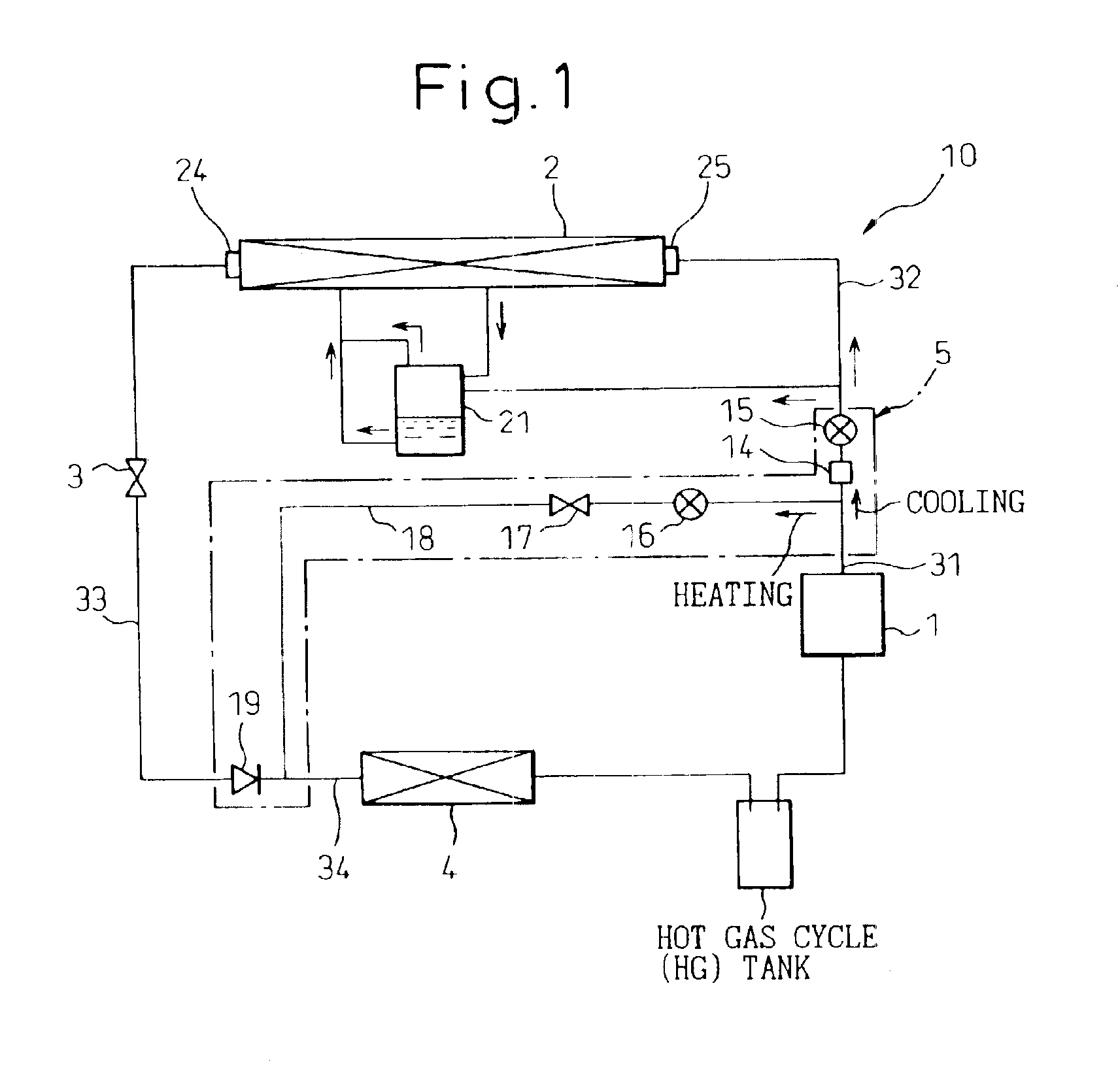
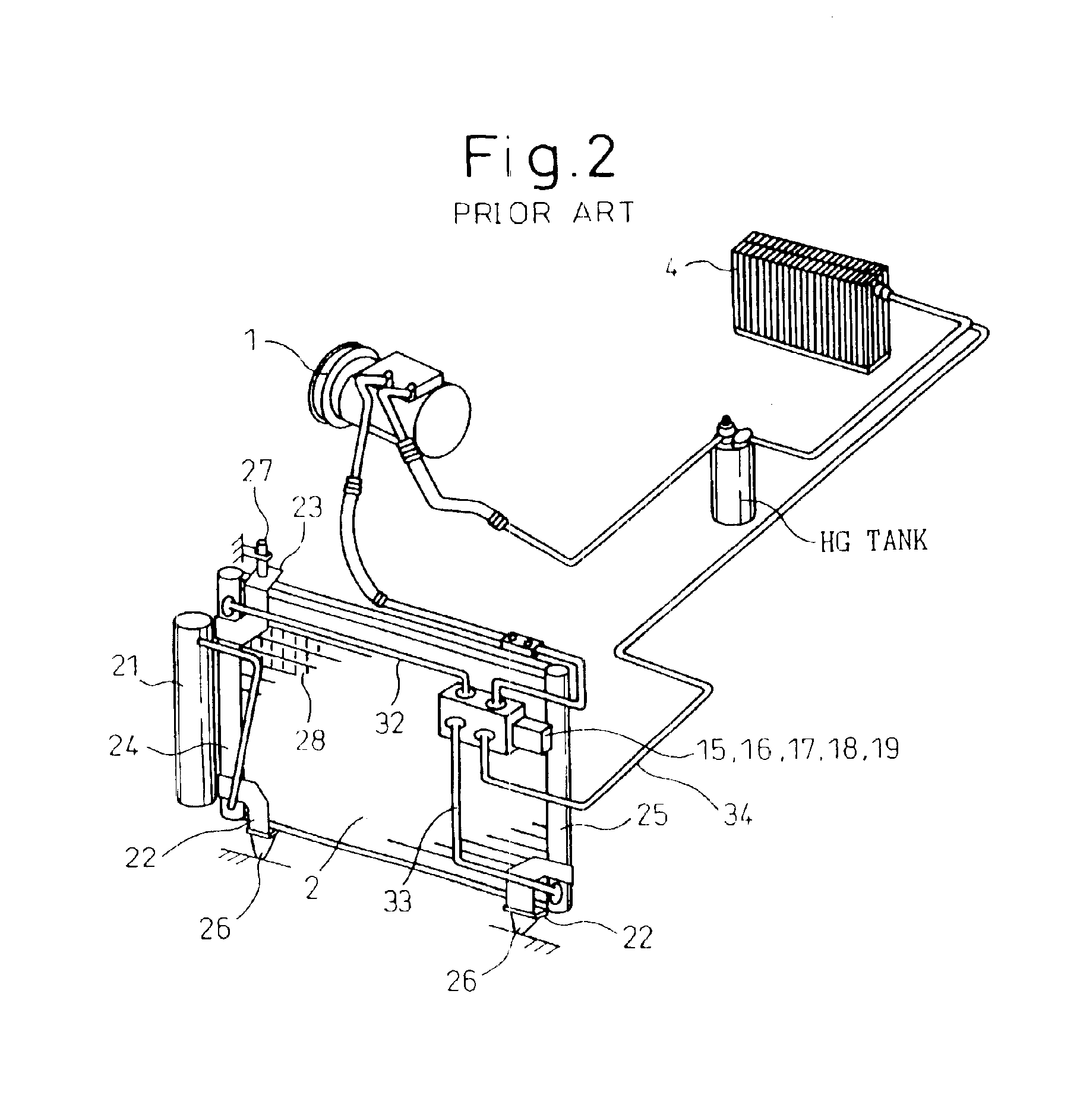
The installation of the valve unit 5 to the condenser of the present invention will be described below in detail based on the embodiments and with reference to the drawings. In FIG. 3, the condenser 2 in the first embodiment is shown and the components of the cooling unit 10 are similar to those of an air conditioner that utilizes a general hot gas cycle shown in FIG. 1 and FIG. 2 are designated by the reference symbols same as those corresponding to the components shown in FIG. 1 and FIG. 2.

As the structure, operation, function, etc. of the air conditioner and the condenser 2 thereof in the first embodiment of the present invention shown in FIG. 3 are basically same as those of the air conditioner, shown in FIG. 1 and FIG. 2, that utilizes a general hot gas cycle, the description of the circuits and structure is given only for the differences between FIG. 3 and FIGS. 1 and 2 to avoid duplication. (This also applies to FIG. 5.)

In the present embodiment, the condenser 2 is a heat exc...

second embodiment

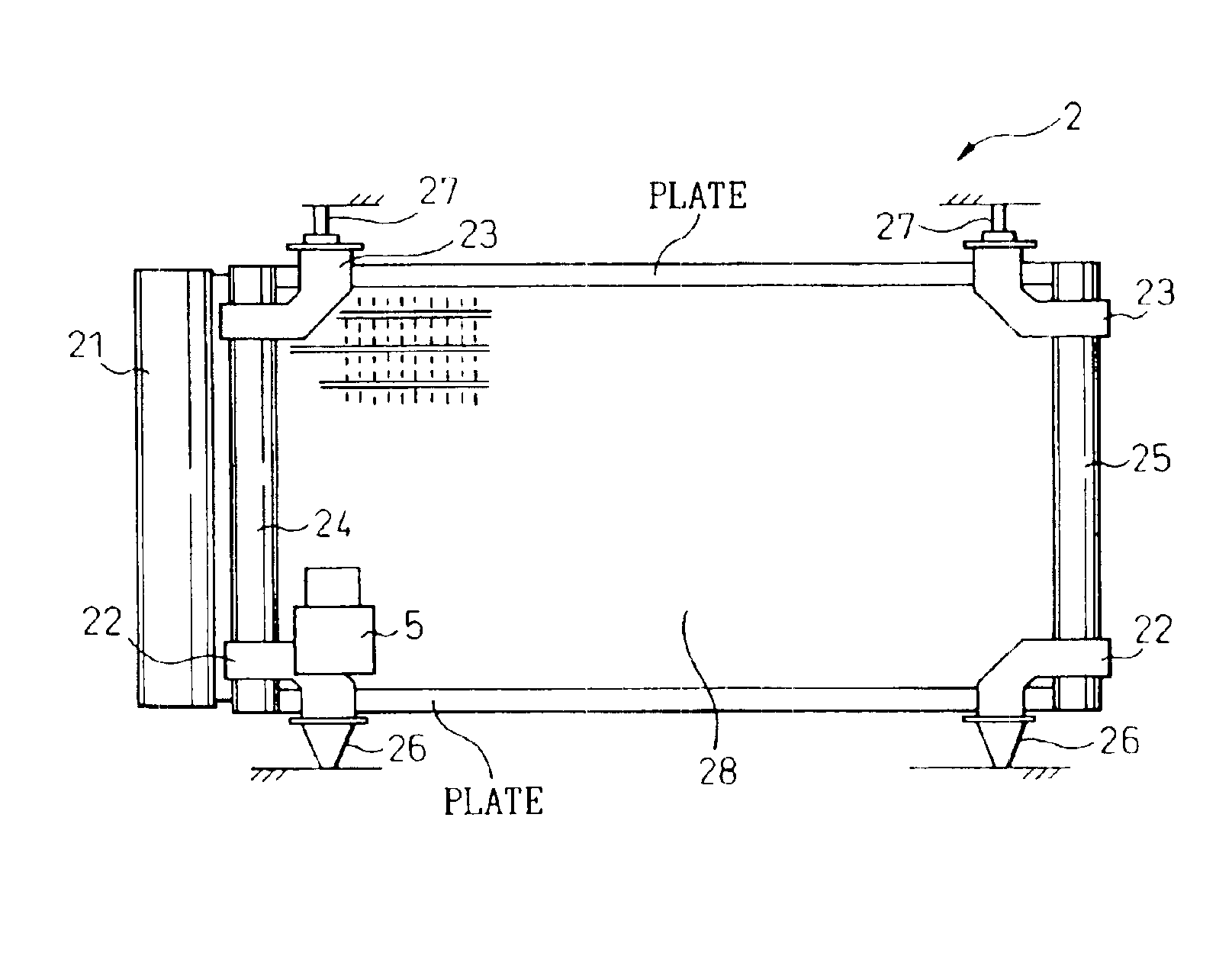
Alternatively, in the present invention the valve unit 5 is fixed to the lower mounting bracket 22, located on the left-hand side, which has a firm structure, as shown in FIG. 5. In this way, parts such as the flexible hoses can also be eliminated in the present invention. Alternatively, the valve unit 5 may be attached to the upper mounting bracket 23 or to the refrigerant tank 21.

Alternatively, the valve unit 5 may comprise piping accessories other than those, such as the pressure sensor 14, provided on the upstream side of the first switching valve 15 on the discharge pipe 31 of the compressor 1, and may exclude some parts of the piping accessories described above.

The first and / or the second switching valves 15 and 16 may be electromagnetic valves. The first switching valve 15 and the second switching valve 16 may be integrally formed into a three way valve. As described above, the valve unit 5 need not contain specific piping components and the components included in the valve u...


PUM


Abstract

A refrigerant circuit in an air conditioner comprises a compressor that compresses a refrigerant, a condenser that liquefies the refrigerant, a pressure reducing device that reduces the pressure of the compressed refrigerant, and an evaporator that exchanges heat by utilizing the refrigerant and generates an air-conditioning air. The condenser comprises plural fin tubes, through which the refrigerant passes, two headers, to which both ends of the fin tubes are connected and which has a firm structure, upper and lower mounting brackets that are fixed to the headers, and vibration insulating materials that collaborate with pin members and support the condenser via the upper and lower mounting brackets. The valve unit is fixed to the header or to the upper or lower mounting bracket.

Description

BACKGROUND OF THE INVENTION1. Field of the InventionThe present invention relates to an air conditioner. Particularly, the present invention relates to an air conditioner for a vehicle. More particularly, the present invention relates to a condenser of an air conditioner for a vehicle and the peripheral piping accessories thereof.2. Description of the Related ArtConventionally, a general air conditioner for a vehicle comprises a cooling unit that cools a compartment by the adiabatic expansion of a refrigerant compressed by a compressor and a heating unit that heats a compartment by the cooling water that has cooled an engine. In this case, it can be said that energy is utilized effectively and also facilities are utilized effectively because the heat of cooling water that cools an engine, which is the power source of the vehicle itself, is utilized as a heat source for heating.Moreover, a hot gas cycle, in which a refrigerant compressed adiabatically by a compressor is directly util...

Claims


Application Information

Patent Timeline
IPC IPC(8): B60H1/32B60H1/00F25B39/04B60H1/22F25B1/00
CPCB60H1/00535F25B39/04B60H1/3229F25B2339/044B60H1/3227
Inventor WANAMI, SHIGEKIKUWAHARA, MIKIHARUKITO, KAZUONAGASAWA, TOSHIYA
Owner DENSO CORP
Why Eureka
Try Eureka