
Flush toilets for RV's and boats

a technology for flushing toilets and rvs, applied in the field can solve the problems of low-water flushing toilets, and achieve the effects of preventing damage to the slide valve, reducing the number of unnecessary costs, and convenient flushing of the toil

Inactive Publication Date: 2005-03-29
THETFORD CORP
View PDF27 Cites 12 Cited by
  • Summary
  • Abstract
  • Description
  • Claims
  • Application Information

AI Technical Summary

Benefits of technology

The slide valve is connected through a clutch to an actuator and this prevents damage to the slide valve in the event of a blockage at the outlet. In such case, the actuator would simply “free wheel” without moving the slide valve.
In light of the above, it is an object of the present invention to provide a toilet that consistently cleans the bowl's surface using a minimum quantity of water. Further, the electronic controls enable easy flushing of the toilet by the user, having only to depress a control button. A second button when depressed adds water to the bowl to enable the user to leave the toilet with the desired amount of water in the bowl.

Problems solved by technology

Water shortages on RV's and boats lead to the use of low-water flush toilets.

Method used


Image

  • Flush toilets for RV's and boats
  • Flush toilets for RV's and boats
  • Flush toilets for RV's and boats

Examples


Embodiment Construction

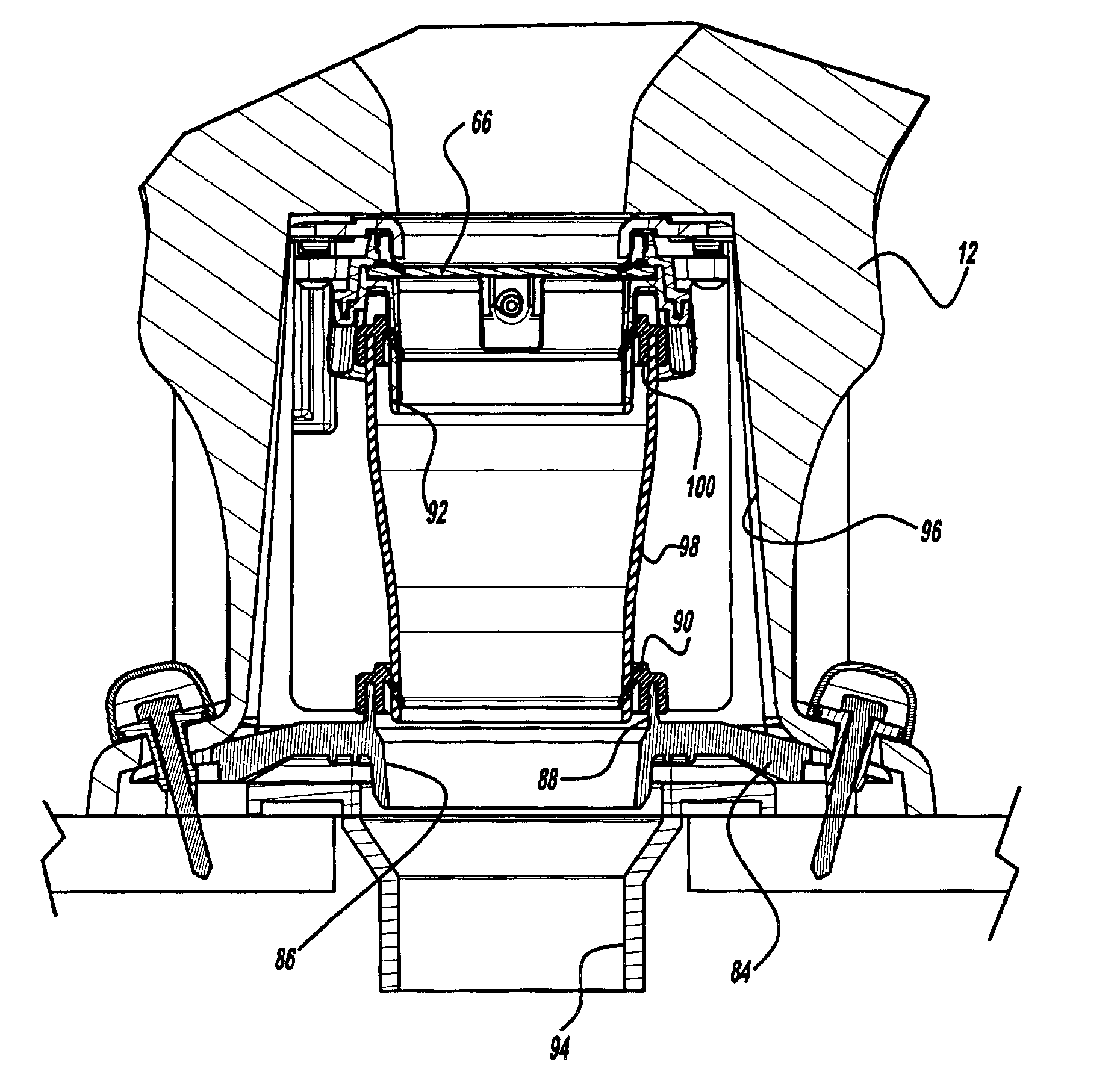
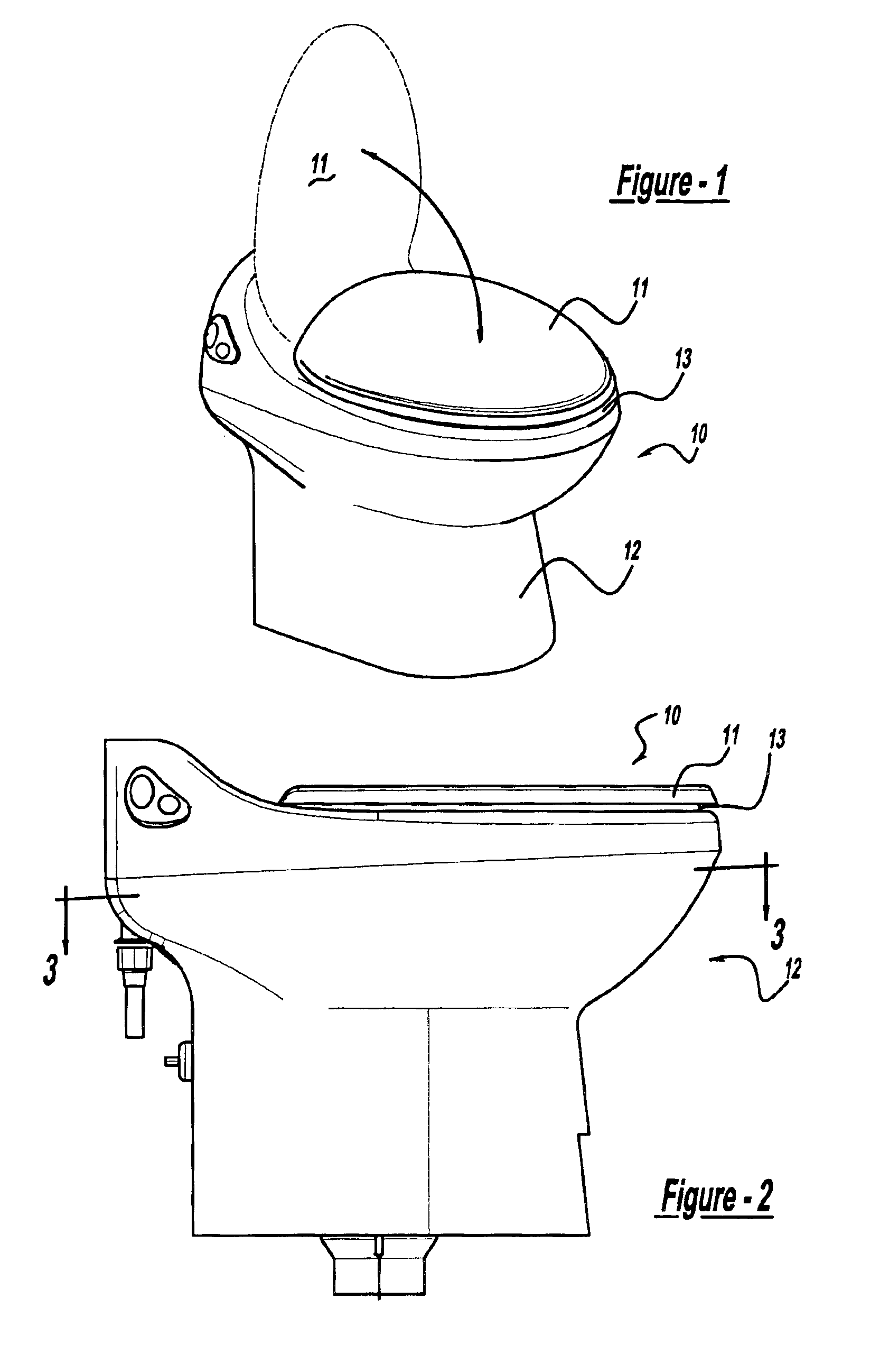
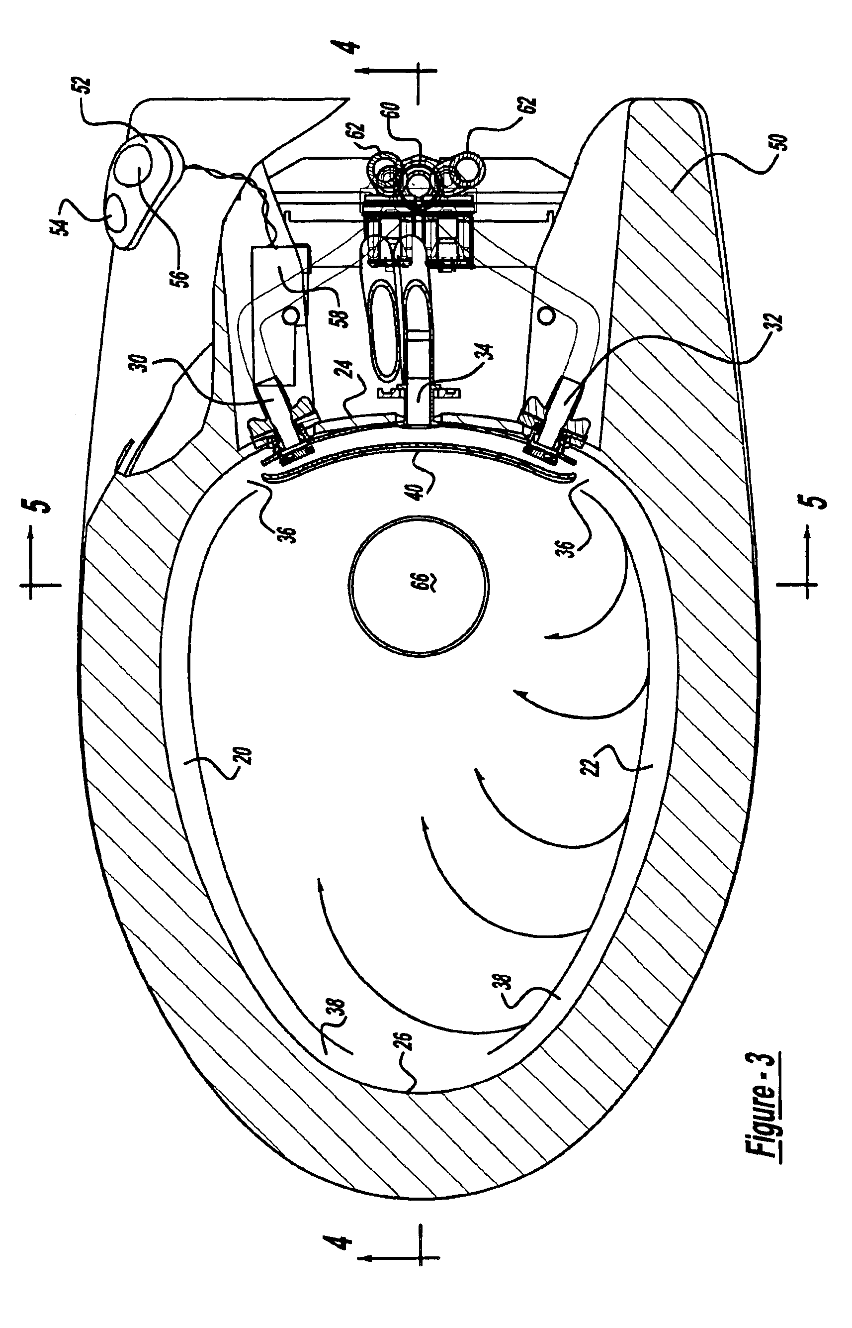
The flush toilet of this invention is shown at FIGS. 1 and 2 and designated generally at 10. The toilet 10 includes a bowl 12 made of china to provide a feeling of being home when using the toilet. The usual cover 11 and seat 13 rest on the bowl 12 when not in use. As shown in FIG. 4, the bowl 12 has an upper end 14 and a lower discharge outlet 16. The inner surface 18 of the bowl 12 is formed with left and right hand ledges 20 and 22 each of which extends from the back 24 of the bowl 12 to the front 26 of the bowl 12. As used throughout the specification and claims the term “ledge” is used to refer to a portion of the bowl surface 18 having a slope or an incline that is closer to horizontal than the slope of the surrounding bowl surface both below and above the ledge.

A nozzle 30 is mounted on the back 24 of the bowl 12 at a position adjacent the end 36 of ledge 20 at the back 24 of the bowl 12. A second nozzle 32 is similarly mounted on the back 24 at a position adjacent the end 36...


PUM


Abstract

A flush toilet having two nozzles located within its bowl. The two nozzles being oriented in opposite directions and alternately providing pulses of flush water into and around the bowl.

Description

BACKGROUND AND SUMMARY OF THE INVENTIONThe present invention relates to a low-water flush toilet and in particular to a toilet providing multiple pulse jets of flush water moving in opposite directions on ledges provided on the toilet bowl near its upper end. The flush water applied to the inner surface of the bowl is carefully controlled to produce consistent and repeatable flushing operations.Water shortages on RV's and boats lead to the use of low-water flush toilets. In some situations, in boats and RV's, conservation of water is essential. The new flush system of this invention is created by providing dual nozzles at the back of the toilet bowl for providing alternating pulses of water from each nozzle, directed so that the water will move along ledges which extends on the sides of the bowl to the front of the bowl, the movement of each pulse of flush water providing for uniformed wetting of one half of the bowl surface below the ledge. The nozzle are directed in opposite direc...

Claims


Application Information

Patent Timeline
IPC IPC(8): E03D3/00E03D5/00E03D11/02E03D5/012E03D11/08
CPCE03D3/00E03D11/08E03D5/012E03D2201/40
Inventor GRECH, GEORGEHAMMOND, JOHN E.MILLER, JAMES KENNETH
Owner THETFORD CORP
Learn More