Marine buoy for offshore support

a technology for buoys and buoys, applied in special-purpose vessels, vessel construction, transportation and packaging, etc., can solve the problems of risky transporting and upending of structures, short response period of platforms,

Inactive Publication Date: 2005-03-22
DEEPWATER MARINE TECH
View PDF18 Cites 25 Cited by
  • Summary
  • Abstract
  • Description
  • Claims
  • Application Information

AI Technical Summary

Benefits of technology

At the base of the elevator shaft is the pump room in which water pumps are used to control the water levels in the lower base section and the upper section ballast chambers. One or more supports are provided which assist in securing the riser and absorbing energy from movement of the platform.
The marine buoy can be constructed and transported in an upright, or vertical, orientation so that it does not need to be upended prior to mooring at its intended location. In addition, structures such as a crane and its pedestal may be placed atop the deck prior to or during transportation of the vessel. During transportation by towing, the floatation tanks of the upper and lower base sections are filled with air so that the lower base section is partially raised above the surface of the water. The marine buoy is placed into its installed position by inserting water ballast into the variable ballast chambers in the upper and lower base section ballast chambers to cause the lower base section to become submerged.

Problems solved by technology

As the water becomes deeper, however, these become impractical, and it is necessary to have a floating platform, or support vessel, upon which the rigs and production facilities can be placed.
Thus, these platforms have a very short period in response to wave action.
As these caisson structures are often around 650 ft. in length, transporting and upending of the structure are risky.

Method used


Image

  • Marine buoy for offshore support
  • Marine buoy for offshore support
  • Marine buoy for offshore support

Examples


Embodiment Construction

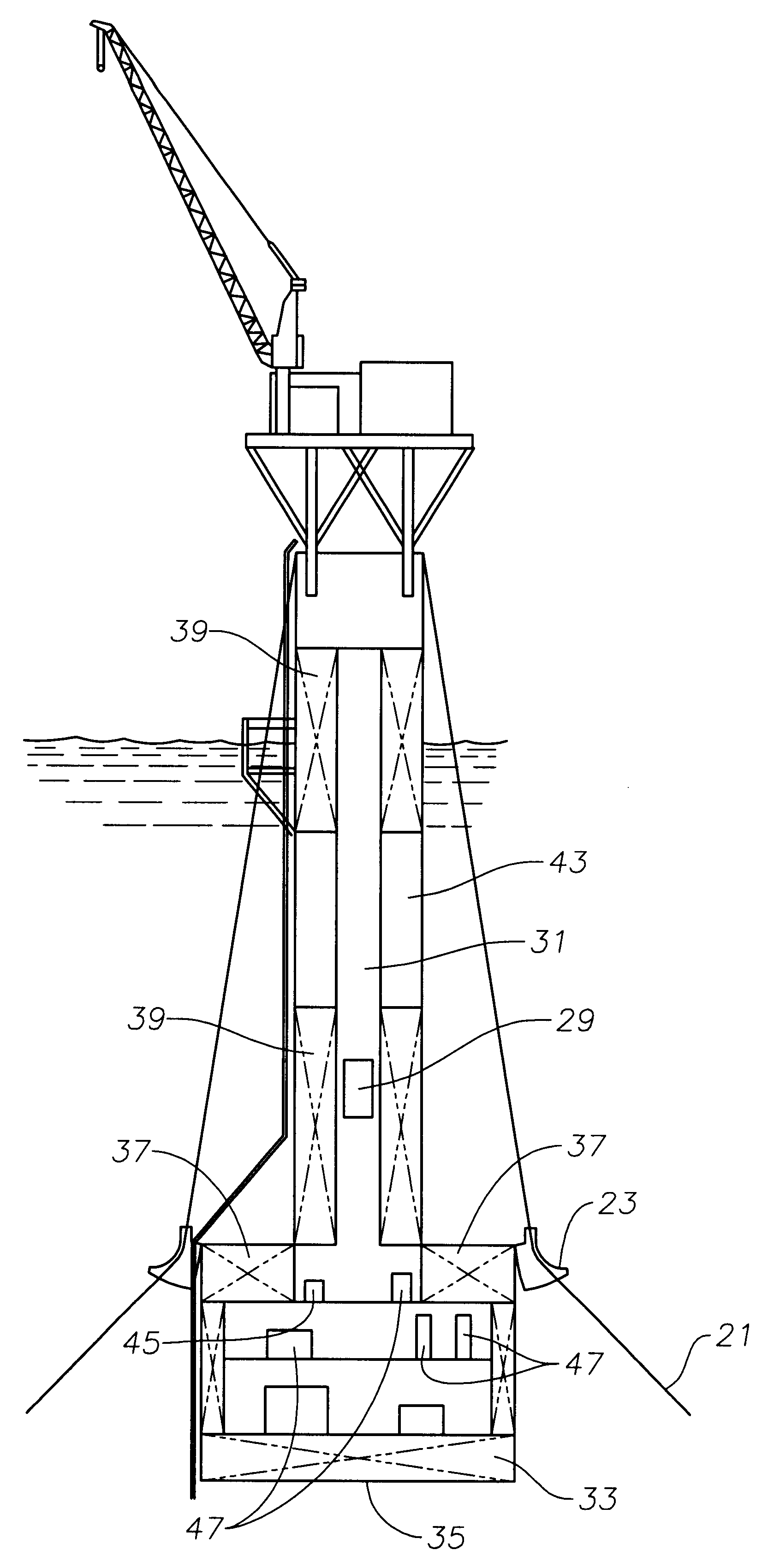
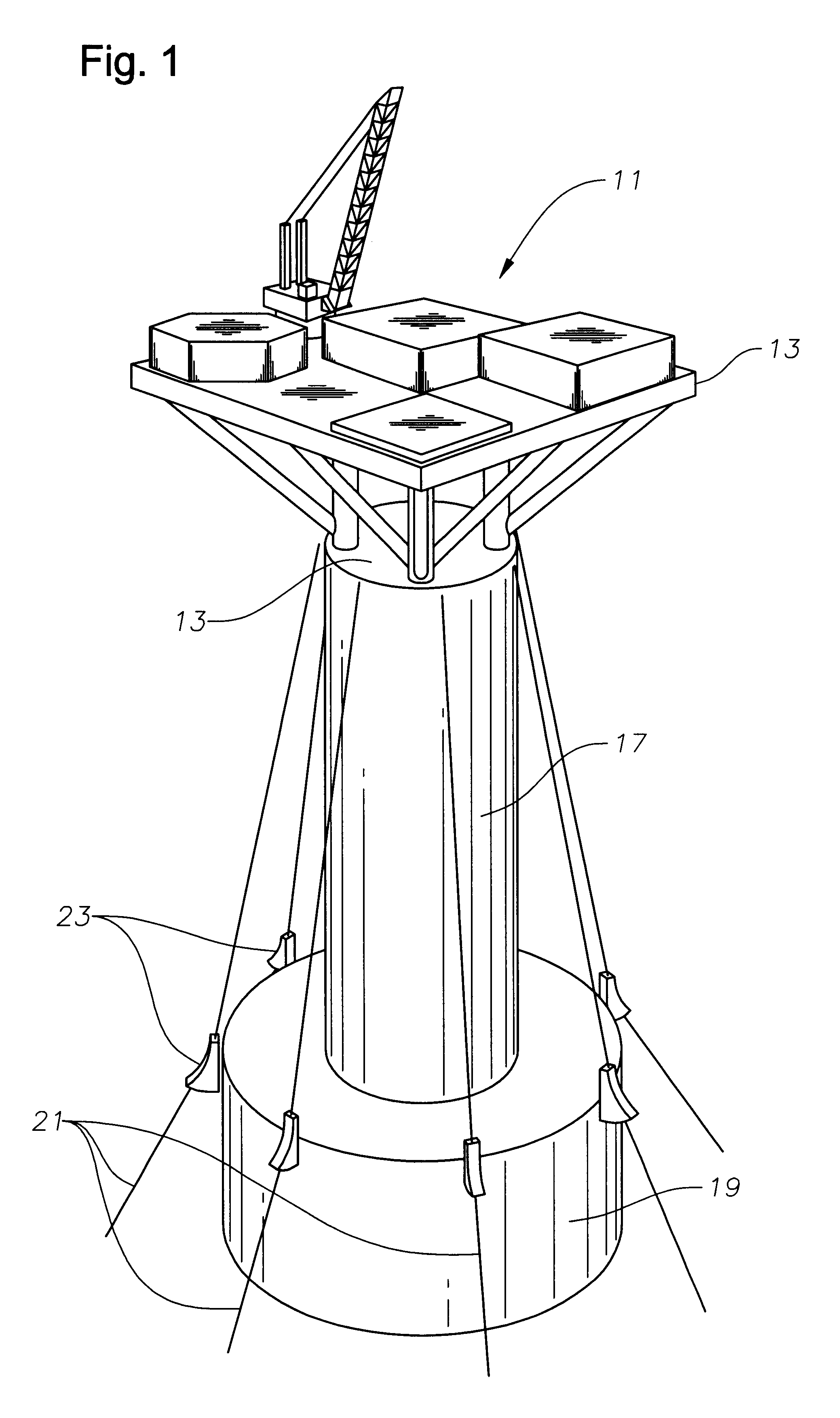
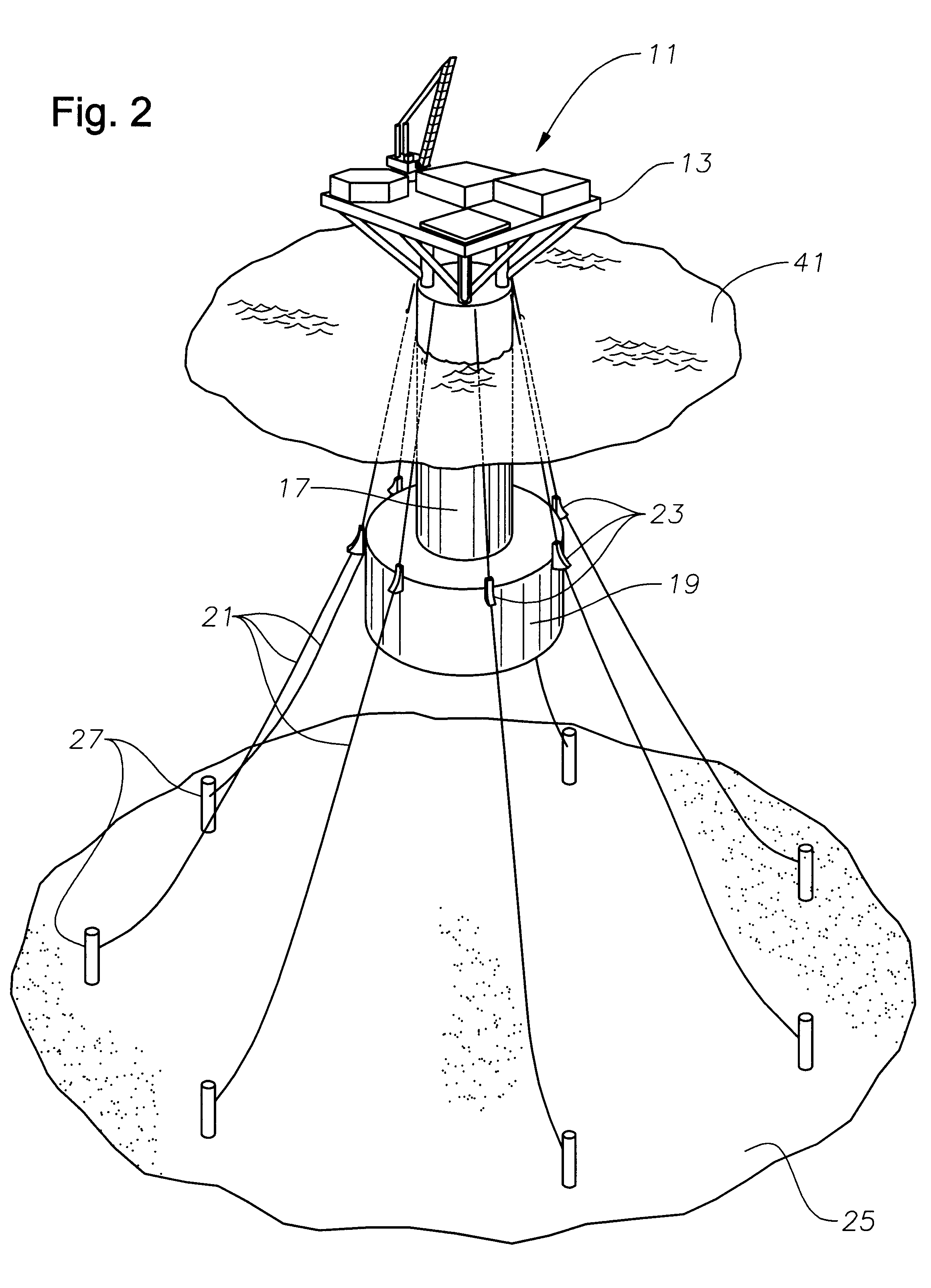
FIGS. 1-2 depict a marine buoy 11 for the support of offshore, subsea drilling operations that is capable of being moored by tethers to the sea floor. The deck 13 of the marine buoy may have constructed upon it power generation equipment, communications and controls equipment, one or more cranes for transferring materials, and other devices and facilities used for supporting the drilling and for production of oil and gas.

Marine buoy 11 has an outer hull 15 and is primarily made up of an upper section 14 and a lower base section 19. Upper base section 17 supports deck 13, upon which the crane, communications equipment, and power generation equipment are secured. Lower base section 19 preferably has a double wall to reduce the risk of leakage in the event of a collision. As shown in FIGS. 1-2, a plurality of mooring lines 21 are secured near the upper end of upper base section 17. The mooring lines 21 extend through bending shoes 23 on lower base section 19 and are then secured in a m...


PUM


Abstract

A marine buoy for the offshore support of subsea production and drilling activities that has a closed-bottomed base section with a solid ballast and variable ballast chambers, a chamber in the base section for storing equipment and supplies, and an upper section with a smaller cross-sectional area than the base section having an elevator shaft leading from the top of the upper section to the chamber in the base section. The upper section supports a deck for housing process equipment for operations that the marine buoy is supporting.

Description

BACKGROUND OF THE INVENTION1. Field of the InventionThe invention relates generally to floating vessels used for supporting offshore drilling operations.2. Description of the Related ArtPetroleum production often requires the placement of a rig in an offshore location. In shallow waters, the rigs and production facilities can be placed on freestanding offshore platforms. As the water becomes deeper, however, these become impractical, and it is necessary to have a floating platform, or support vessel, upon which the rigs and production facilities can be placed.One type of deepwater support vessel is the tension leg platform (TLP). The TLP is a buoyant platform that is secured to the seabed using generally vertically-oriented rigid tethers or rods that restrain the platform against vertical and horizontal motion relative to the well in the seabed below. Thus, these platforms have a very short period in response to wave action.An alternative to the TLP is the deep draft caisson vessel ...

Claims


Application Information

Patent Timeline
Patent Type & Authority Patents(United States)
IPC IPC(8): B63B1/00B63B17/00B63B35/44B63B1/04E21B19/00
CPCB63B1/048B63B17/00E21B19/006B63B39/005B63B35/4413B63B2001/044
Inventor ZOU, JUNHUANG, EDWARDANDERSON, CLAY F.ALLEN, JOHN
Owner DEEPWATER MARINE TECH
Why Eureka
Try Eureka