Eureka AIR delivers breakthrough ideas for toughest innovation challenges, trusted by R&D personnel around the world.

Vehicle front end structure

a front end structure and vehicle technology, applied in the direction of roofs, vehicle arrangements, transportation and packaging, etc., can solve the problems of large repairing cost and easy breakage of the attaching portion of the carrier

Inactive Publication Date: 2005-03-22
DENSO CORP
View PDF11 Cites 22 Cited by
  • Summary
  • Abstract
  • Description
  • Claims
  • Application Information

AI Technical Summary

Benefits of technology

In view of the above problem, the first object of the present invention is to provide a new vehicle front end structure different from a conventional one, and the second object is to prevent a carrier from being broken when a collision occurs.
Therefore, the attaching portions of the carrier (1) are seldom broken because the action of a large impulsive force on the carrier (1) can be prevented when a collision occurs. Accordingly, the carrier (1) is prevented from being broken when a light collision occurs, and a new front end structure of a vehicle different from a conventional front end structure can be obtained. The necessary rigidity of the carrier (1) can be reduced to the rigidity necessary to support a functional component such as a radiator or a condenser because the rigidity of a vehicle body can be increased by the reinforcing member portion (4a). Thus, the weight of the carrier (1) can be reduced.

Problems solved by technology

Thus, the attaching portions of the carrier are easily broken.
Accordingly, a large repairing cost is incurred even when a light collision occurs.

Method used


Image

  • Vehicle front end structure
  • Vehicle front end structure
  • Vehicle front end structure

Examples


first embodiment

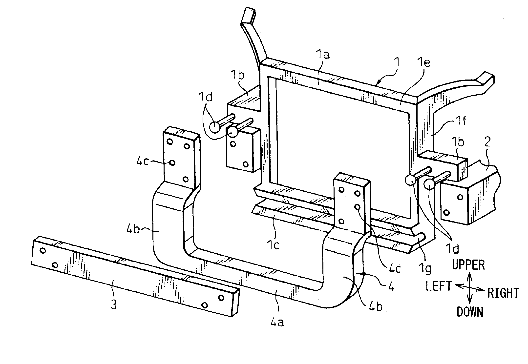
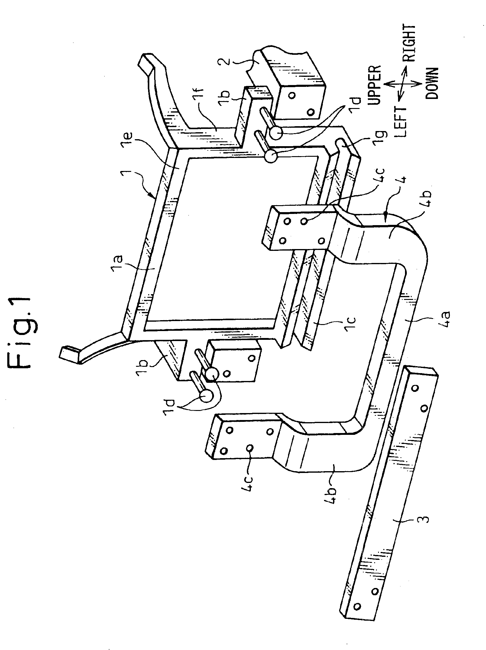
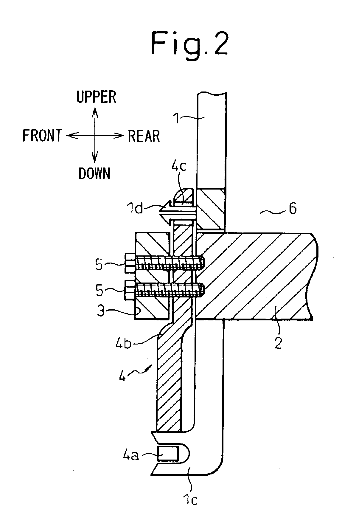
FIG. 1 is an exploded perspective view of a vehicle front end structure according to the present embodiment, and FIG. 2 is a sectional view of the vehicle front end structure according to the present embodiment.

A heat exchanger such as a radiator or a condenser and a component mounted to the vehicle front end side, such as a headlight, are attached to a carrier 1. The carrier 1 is an integral unit composed of a carrier main body 1a that functions as a rectangular frame, brackets 1b for attaching the carrier 1 and a shroud for a radiator. A carrier main body 1a is composed of an upper beam portion 1e extending in the vehicle width direction, a lower beam portion 1c and columnar portions 1f for connecting the upper beam portion 1e and the lower beam portion 1c. A groove 1g is formed in the lower beam portion 1c, in a longitudinal direction thereof.

In the present embodiment, the carrier 1 is made of a resin, having a mechanical strength, reinforced by fibers of high tensile strength, s...

second embodiment

As shown in FIG. 3, in the present embodiment, a cushioning member 7 for absorbing an impact force is provided at contact points between the carrier 1 and the bracket 4.

The cushioning member 7 is made of a material, that is more easily broken than the bumper reinforcement 3 or the bracket 4 made of resin or the like, such as an elastic material having spring characteristics or a material having a shape to exhibit spring characteristics.

third embodiment

As shown in FIG. 4, in the present embodiment, a cushioning portion 4d for absorbing a collision force is provided on the surface of the bracket 4 opposite to the bumper reinforcement 3.

It is needless to say that a cushioning member, such as a crush box, for absorbing a collision force may be held between the bumper reinforcement 3 and the bracket 4.


PUM


Abstract

A carrier (1) is secured to a vehicle front end portion via a bracket (4) secured to side members (2) and a bumper reinforcement (3). The connecting portions of the carrier (1) to the bracket (4) are deviated from the side members (2) when viewed from the front side of a vehicle. The bracket (4) is provided with a reinforcing member portion (4a) to connect the left and right side members (2). Accordingly, the action of a large impact force on the carrier (1) can be prevented because only a collision force from the bumper reinforcement (3) acts on the carrier (1) and no reaction force, from the side members, acts on the carrier, when a collision occurs. Therefore, the carrier (1) can be prevented from being broken when a light collision occurs because the attaching portions of the carrier (1) are seldom broken. The rigidity of a vehicle body can be increased by the reinforcing member portion (4a), and the necessary rigidity of the carrier (1) can be reduced. Thus, the weight of the carrier (1) can be reduced.

Description

TECHNICAL FIELDThe present invention relates to a front end structure of a vehicle.BACKGROUND ARTIn a general front end structure of a vehicle, as shown in FIGS. 6A and 6B, a carrier 1 is held between, and secured to, a side member 2 and a bumper reinforcement 3.In some literature, the carrier is called “front end panel” or “radiator support”, and is in the shape of a panel, a beam or a rectangular frame, which extends in a width direction of the vehicle, at the vehicle front end portion. The side members are columnar reinforcing members which are positioned on lateral sides of the vehicle and receive a buckling load. The bumper reinforcement is a beam-like reinforcing member which is positioned at the vehicle front end portion and receives a bending load.In a conventional structure shown in FIGS. 6A and 6B, the carrier 1 is held between and secured to the side members 2 and the bumper reinforcement 3. Accordingly, when a collision force acts on the vehicle front end side, a collisi...

Claims


Application Information

Patent Timeline
IPC IPC(8): B62D25/08
CPCB62D25/084
Inventor KAFUKU, KAZUAKIOKAI, HARUMI
Owner DENSO CORP
Why Eureka
Eureka Blog
Learn More