Inner panel for a vehicle door

a technology for inner panels and vehicles, applied in the direction of doors, roofs, pedestrian/occupant safety arrangements, etc., can solve the problems of giving this beam a high degree of rigidity or stiffness, and achieve the effect of simplifying a construction

Inactive Publication Date: 2005-03-22
SSAB HARDTECH AB
View PDF16 Cites 24 Cited by
  • Summary
  • Abstract
  • Description
  • Claims
  • Application Information

AI Technical Summary

Problems solved by technology

However, it is disadvantageous to give this beam a high degree of rigidity or stiffness, since it is desirable for the door to yield in the event of a side-on impact.

Method used


Image

  • Inner panel for a vehicle door
  • Inner panel for a vehicle door
  • Inner panel for a vehicle door

Examples


Embodiment Construction

. 1

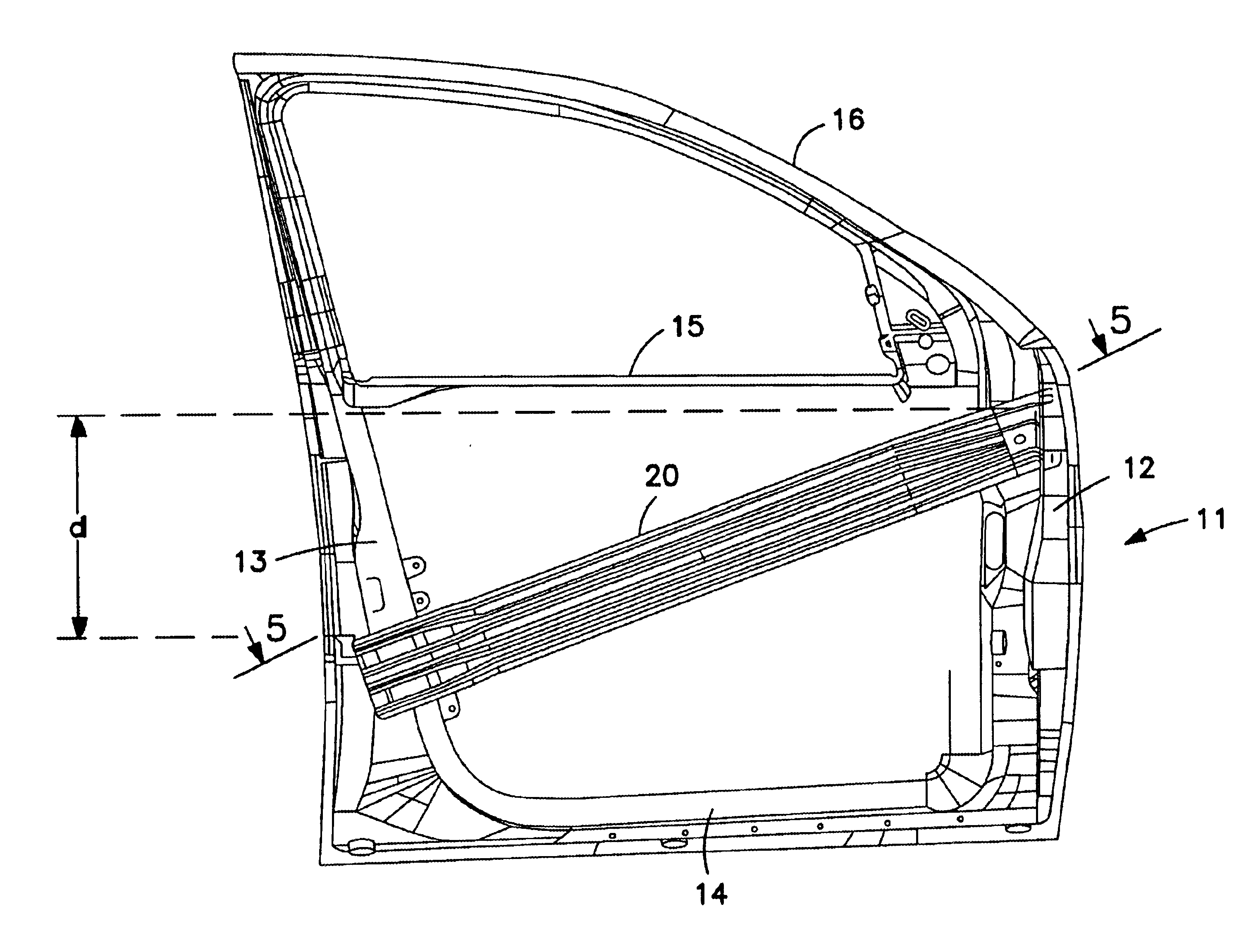
FIG. 1 shows the inner panel 11 of a vehicle door as seen from the outside. The inner panel has a front end wall 12, a rear end wall 13, a bottom 14, a beam 15 (waist beam or waist rail) and a window arch 16. The inner panel has a side 17 which faces towards the vehicle interior and which includes a number of holes and recesses. These holes and recesses are not shown in FIG. 1, but are shown in FIG. 5. The holes are required for mounting all door fittings. A stiffening or reinforcing beam 20 is fitted between the front end wall and rear end wall and slopes rearwardly. As shown in FIG. 1, the front end of the reinforcement beam 20 is connected to the front end wall 12 at an elevation above the midpoint of the front end wall, and the rear end of the reinforcement beam 20 is connected to the rear end wall 13 at an elevation below the midpoint of the rear end wall. The front end of the reinforcement beam 20 is elevated above the rear end of the reinforcement beam 20 by a distance des...


PUM


Abstract

A vehicle door has an inner panel (11) on which an outer panel is fitted. The inner panel is covered by a loose panel, the trim. The inner panel has a front end wall (12) and a rear end wall (13). A reinforcement beam (20) is fastened between the end walls for transmitting force from a door pillar (33) to which the door is attached to a door pillar (34) behind the door, in the event of a collision. The reinforcement beam has a high single hat profile (21) which is fastened to the upper part of the front end wall, and extends in a curve out towards the external part of the inner panel, where the profile height is lower. The profile height decreases continuously from the high profile height to the low profile height, and the single hat profile (21) extends into a double hat profile (22). The reinforcement beam also functions as a side impact guard.

Description

FIELD OF INVENTIONThe present invention relates to a vehicle door inner panel comprising a front end wall, a rear end wall and a reinforcing beam attached between said walls, such as to enable impact forces emanating from a collision to be transmitted from the door pillar or pillar to which the door is attached to the door pillar situated behind the door.DESCRIPTION OF THE BACKGROUND ARTCar doors are typically comprised of an inner panel, which forms the supportive part of the door, and a lacquered outer panel. The inner panel is covered with a detachable panel, i.e. so-called trim.In the construction of a car, it can be chosen to allow the door to transmit force or load from the A-pillar to the B-pillar, in the event of a frontal collision. A-pillar is the accepted designation of the windscreen-adjacent pillar on which the front door is hung, while B-pillar is the designation of the pillar situated behind the front door, i.e. between the doors when two doors are situated on respect...

Claims


Application Information

Patent Timeline
Patent Type & Authority Patents(United States)
IPC IPC(8): B60R21/04B60J5/04B60J5/00
CPCB60J5/0437B60R21/0428B60J5/0444B60J5/04
Inventor BODIN, HANSAKERSTROM, PAUL
Owner SSAB HARDTECH AB
Why Eureka
Try Eureka