Entry-driving machine and cutting part thereof

A technology of cutting part and cutting head, which is applied in the directions of slitting machinery, driving device, earth-moving drilling, etc., can solve the problems of complicated layout of internal spray water channels, increasing the manufacturing cost of the cutting part, and increasing the complexity of the cutting part, etc. , to achieve the effect of avoiding interference or damage, low manufacturing cost, and easy space layout

Inactive Publication Date: 2012-03-14
SANY HEAVY EQUIP
View PDF5 Cites 5 Cited by
  • Summary
  • Abstract
  • Description
  • Claims
  • Application Information

AI Technical Summary

Problems solved by technology

Apparently, the arrangement of the inner spray channel in the above-mentioned cutting part is rather cumbersome, and this arrangement increases the complexity of the cutting part while increasing the manufacturing cost of the cutting part and reduces the practicability of the cutting part

Method used


Image

  • Entry-driving machine and cutting part thereof
  • Entry-driving machine and cutting part thereof
  • Entry-driving machine and cutting part thereof

Examples


Embodiment Construction

[0024] The core of the present invention is to provide a cutting part of construction machinery, the cutting part has a small height, improved working performance, convenient arrangement of the inner spray water channel, and high versatility and practicability. Another core of the present invention is to provide a boring machine with the above-mentioned cutting portion.

[0025] In order to enable those skilled in the art to better understand the technical solutions of the present invention, the present invention will be further described in detail below in conjunction with the accompanying drawings and specific embodiments.

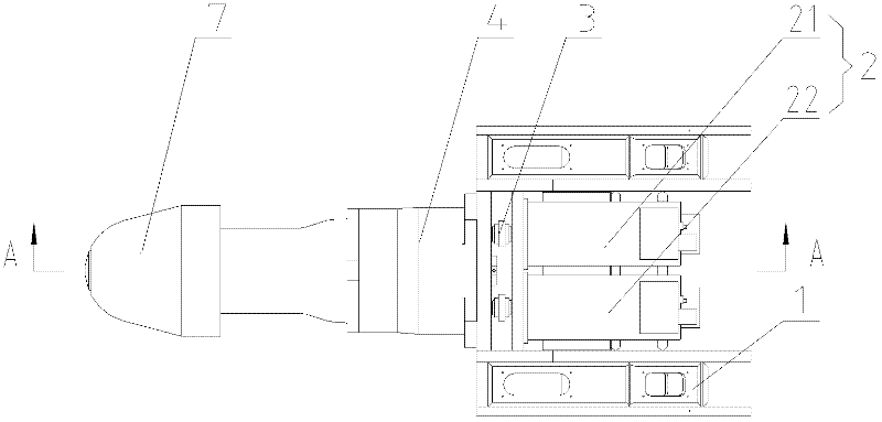
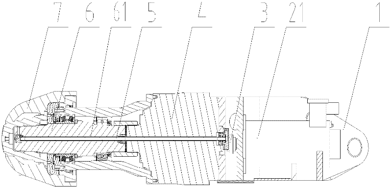
[0026] see figure 1 , figure 2 and image 3 , figure 1 It is a structural schematic diagram of a specific embodiment of the cutting part provided by the present invention, figure 2 for figure 1 A-A sectional schematic diagram of image 3 It is a structural schematic diagram of a specific embodiment of the reducer provided by the present invention...


PUM


Abstract

The invention discloses a cutting part of an engineering machine. The cutting part comprises a cutting head, a cutting head shaft, a water pipe, a speed reducer, at least two power devices for driving the cutting head and an installation rack, wherein the installation is fixed on the power devices; the output ends of the power devices are connected with the input end of the speed reducer; and the output end of the speed reducer is in fixed connection with the cutting head through the cutting head shaft. The invention also discloses an entry-driving machine comprising the cutting part. In the cutting part of the entry-driving machine, the output shafts of at least two power devices are in corresponding connection with the input shafts of the speed reducer, the power devices drive the speed reducer to work, after speed reduction and moment increase of the speed reducer, the cutting head shaft connected with the output shaft of the speed reducer rotates, and thus the cutting head is driven to rotate. The cutting part disclosed by the invention has the characteristics that: along with the height decrease, the working performance is increased, the cutting part can work in a narrow space and the universality is significantly improved; and furthermore, by the cutting part, the arrangement of an internal spraying water channel is simplified.

Description

technical field [0001] The invention relates to the technical field of engineering machinery, in particular to a cutting part of an engineering machinery. The invention also relates to a road boring machine with a cutting section as described above. Background technique [0002] The cutting part is the general name of the working mechanism of the mining machinery and the transmission device, driving device and accessory device of the working mechanism, and is the key mechanism in the mining machinery. As a more commonly used mechanical equipment in mining machinery, roadheaders are mainly composed of cutting parts, loading parts, scraper conveyors, walking parts, racks, rotary tables, hydraulic systems, water systems and electrical systems. [0003] The cutting part is mainly composed of motor, fork frame, reducer, cutting head shaft and cutting head. The entire cutting part is hinged on the turntable through the fork frame and the pin shaft. The motor is installed on the...

Claims


Application Information

Patent Timeline
Patent Type & Authority Applications(China)
IPC IPC(8): E21C31/02E21C35/04
Inventor 李恩龙支建燊温保岗
Owner SANY HEAVY EQUIP
Why Eureka
Try Eureka