Assemblies comprising fastener with ergonomically balanced removal to insertion ratio
Inactive Publication Date: 2005-03-22
TERMAX CORP +1
View PDF34 Cites 39 Cited by
- Summary
- Abstract
- Description
- Claims
- Application Information
AI Technical Summary
Benefits of technology
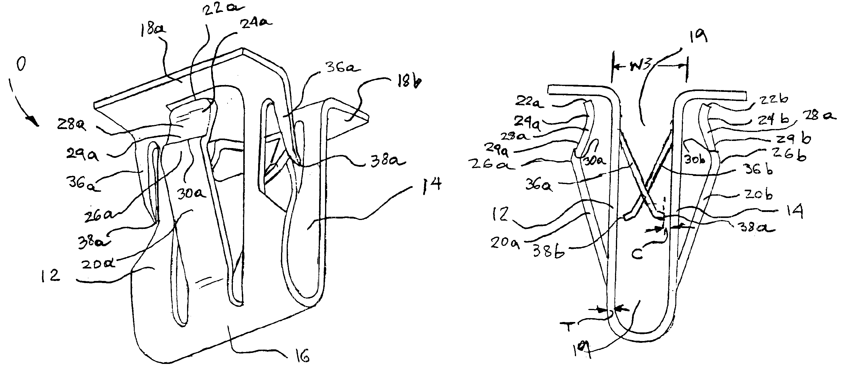
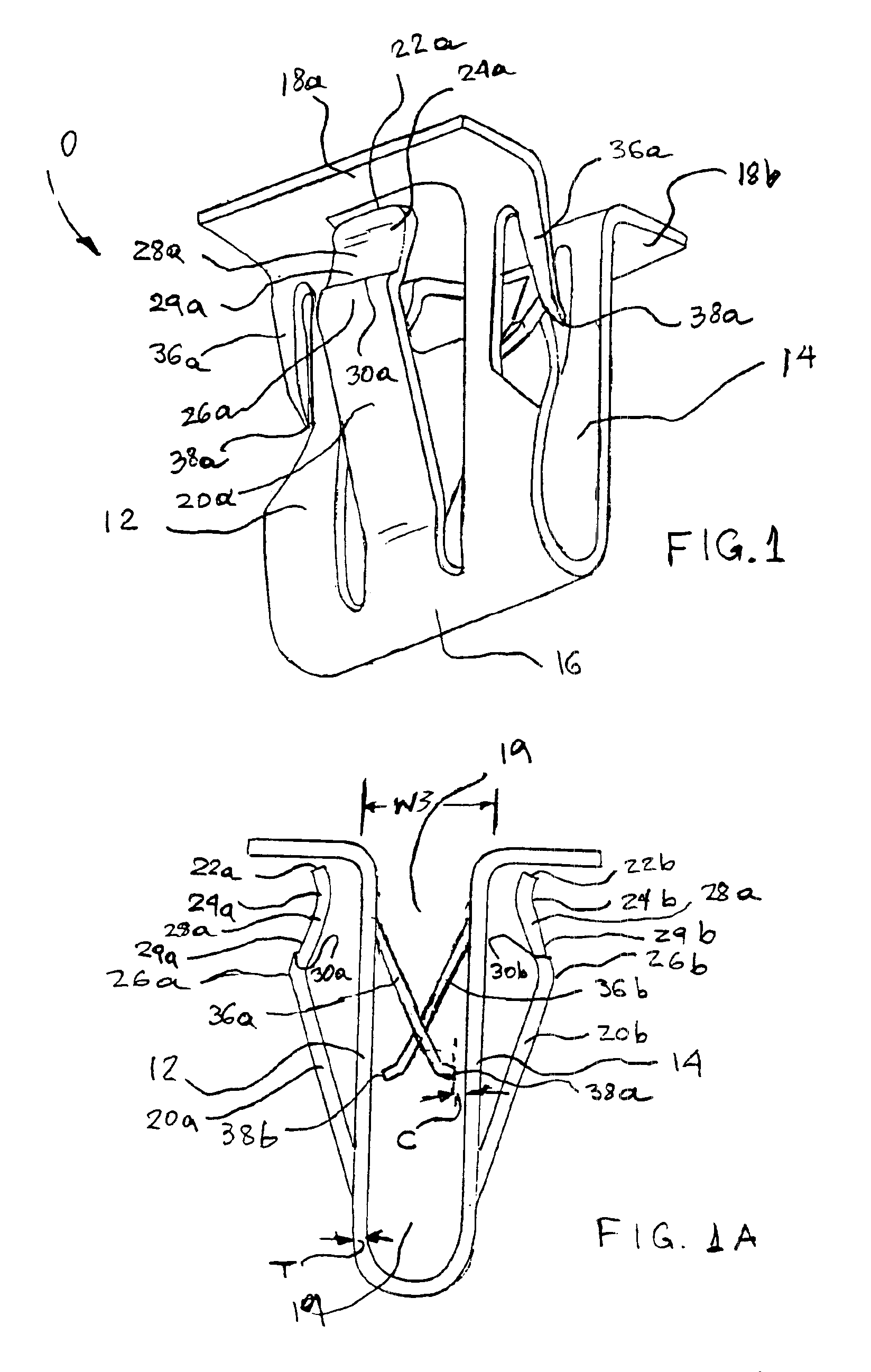
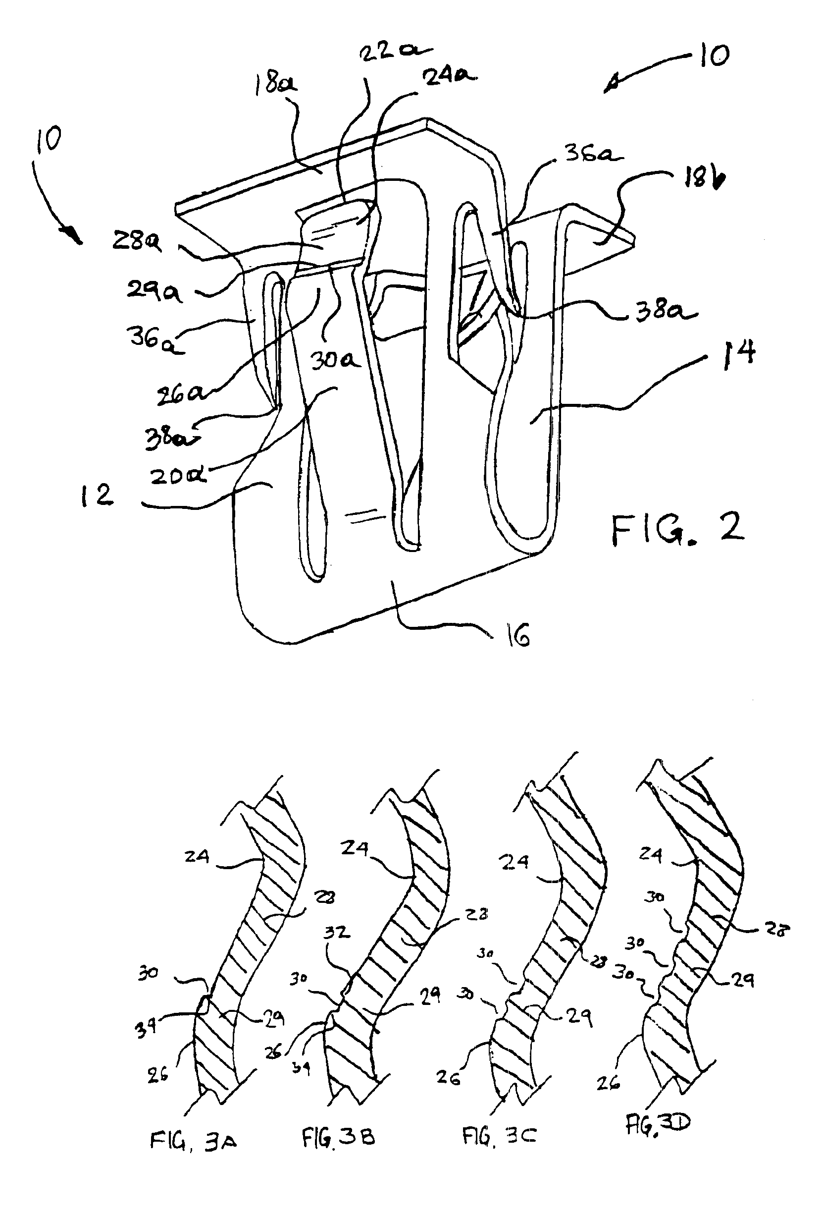
More particularly, the invention pertains a spring fastener comprising a first side and a second side opposite the first side, the first side connected to the second side thereby forming a U-shaped structure having a cavity between the first side and the second side, a bottom portion wherein the first side and the second side are connected, and a top portion, the first side comprising first barbs having first front ends, and a first engagement spring, the first engagement spring connected to the first side in the vicinity of the bottom portion, the second side comprising second barbs second front ends, and a second engagement spring, the second engagement spring connected to the second side in the vicinity of the bottom portion, each of the first and second engagement springs having a recess and a free end in the vicinity of the top portion, each spring also comprising a peak and an engagement region with a hindrance portion between the recess and the peak, the hindrance portion providing increased removal force, when the fastener is pulled by a rib of a first part engaged to the first and second barbs, after the fastener has been inserted into a slot of a second part, the slot having a slot width and edges on which edges the engagement region is engaged, the increased removal force being due to the hindrance portion, and wherein the fastener can be extracted when pulled by the rib without damage to said fastener.
Problems solved by technology
This is ergonomically inferior performance, and the operators may suffer miscellaneous ailments, while productivity is also considerably undermined.
However, “bulbous projections” are necessarily voluminous, take most of the space between the “reverse bents”, and unless they are manufactured within tight tolerances with regard to the thickness of the frame, the “base plates” do not sit on the frame (see also the Figures), rendering the structure unstable.
Method used
View moreImage
Smart ImageViewing Examples
Examples
examples of embodiments demonstrating
the operation of the instant invention, have been given for illustration purposes only, and should not be construed as restricting the scope or limits of this invention in any way.
Login to View More PUM
 Abstract
Assemblies comprising a fastener, which has engagement springs in opposite sides of the fastener. Each engagement spring has an engagement region comprising a hindrance portion, which increases considerably the removal to insertion force ratio as compared to such ratio in the absence of the hindrance portion, thus permitting very easy insertion with considerably more difficult removal of the fastener from the slot of a panel, which provides an efficient ergonomically balanced removal to insertion force ratio. The hindrance portion comprises ripples or other hindrance elements of unexpectedly minute dimensions for providing this efficient ergonomic force balance.
Description
FIELD OF THE INVENTIONThis invention relates to spring fasteners characterized by a structure having a cavity in which an extension or rib of a first part, such as a plastic panel for example, may be engaged, and they are also suitable to be engaged reversibly in a slot of second part, such as a metal sheet or the frame of a car for example. The invention also pertains an assembly of the first and the second part as connected to each other through the fastener, as well as vehicles comprising such assemblies.BACKGROUND OF THE INVENTIONA number of fasteners have been used in the past for securing one object on another object, as for example, securing an article such as for example a plastic sheet on a metal or other rigid plastic sheet. However, the fasteners of the type, which are improved by the advances of the present invention, and being used presently, have a rather low ratio of insertion force to removal force. In other words, they require considerable force to be inserted into ...
Claims
Login to View More Application Information
Patent Timeline
 IPC IPC(8): F16B21/00F16B21/08F16B5/06
CPCF16B5/0614F16B21/075Y10T24/307Y10T24/30Y10T403/7176Y10T24/4453Y10T24/304Y10T24/306Y10T24/44026
Inventor DICKINSON, DANIEL JAMESSMITH, MICHAEL WALTERCONWAY, LAWRENCE JOHNSACHA, EDWARDCLEMENS, PAUL LESTERFLEYDERVISH, MARKDUCATO, RICHARD H.VASSILIOU, EUSTATHIOS
Owner TERMAX CORP
Features
- R&D
- Intellectual Property
- Life Sciences
- Materials
- Tech Scout
- Unparalleled Data Quality
- Higher Quality Content
- 60% Fewer Hallucinations
Learn More Browse by: Latest US Patents, China's latest patents, Technical Efficacy Thesaurus, Application Domain, Technology Topic, Popular Technical Reports.
© 2025 PatSnap. All rights reserved.Legal|Privacy policy|Modern Slavery Act Transparency Statement|Sitemap|About US| Contact US: help@patsnap.com


