
Method, processor and computed tomography (CT) machine for generating images utilizing high and low sensitivity data collected from a flat panel detector having an extended dynamic range

a computed tomography and dynamic range technology, applied in the field of methods, processors and computed tomography machines for generating images utilizing high and low sensitivity data collected from flat panel detectors having an extended dynamic rang

Inactive Publication Date: 2005-03-15
RGT UNIV OF MICHIGAN
View PDF43 Cites 61 Cited by
  • Summary
  • Abstract
  • Description
  • Claims
  • Application Information

AI Technical Summary

Problems solved by technology

However, their use in tomography has been hampered by various problems, such as gain and offset fluctuations, image lag, readout noise, slow readout rate, etc.
One of the major problems is an inadequate dynamic range of FPIs for most tomographic applications which require a good low contrast resolution.
One faces an analogous problem in photography—when the photographed scene has both high and low light areas, parts of the photograph will appear either as too bright, or even uniformly white, due to overexposure, or too dark, or even uniformly black due to underexposure.
As noted by Nayar [2], a major disadvantage of these methods is their cost due to the need for multiple detectors, precision alignment optics and additional image capture hardware.

Method used


Image

  • Method, processor and computed tomography (CT) machine for generating images utilizing high and low sensitivity data collected from a flat panel detector having an extended dynamic range
  • Method, processor and computed tomography (CT) machine for generating images utilizing high and low sensitivity data collected from a flat panel detector having an extended dynamic range
  • Method, processor and computed tomography (CT) machine for generating images utilizing high and low sensitivity data collected from a flat panel detector having an extended dynamic range

Examples


Embodiment Construction

In general, the present invention extends the dynamic range of flat panel detectors. It consists of two parts: 1) hardware modifications on the detector; and 2) software method of combining the signals that the detector outputs. Several hardware modifications and several software method are proposed. Each of the hardware methods can be used in combination with each of the software methods. Also, the hardware methods can be combined between themselves in addition to being combined with a software method. Finally, a method is proposed for automatic estimation of the parameters used in hardware modifications 1 and 2.

Hardware Modifications

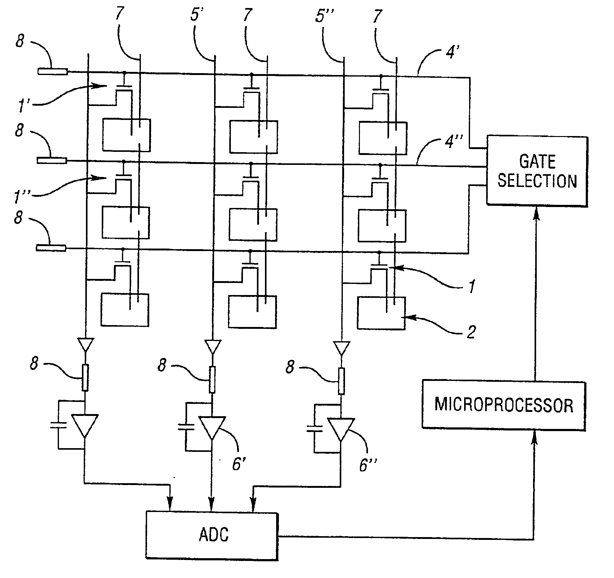
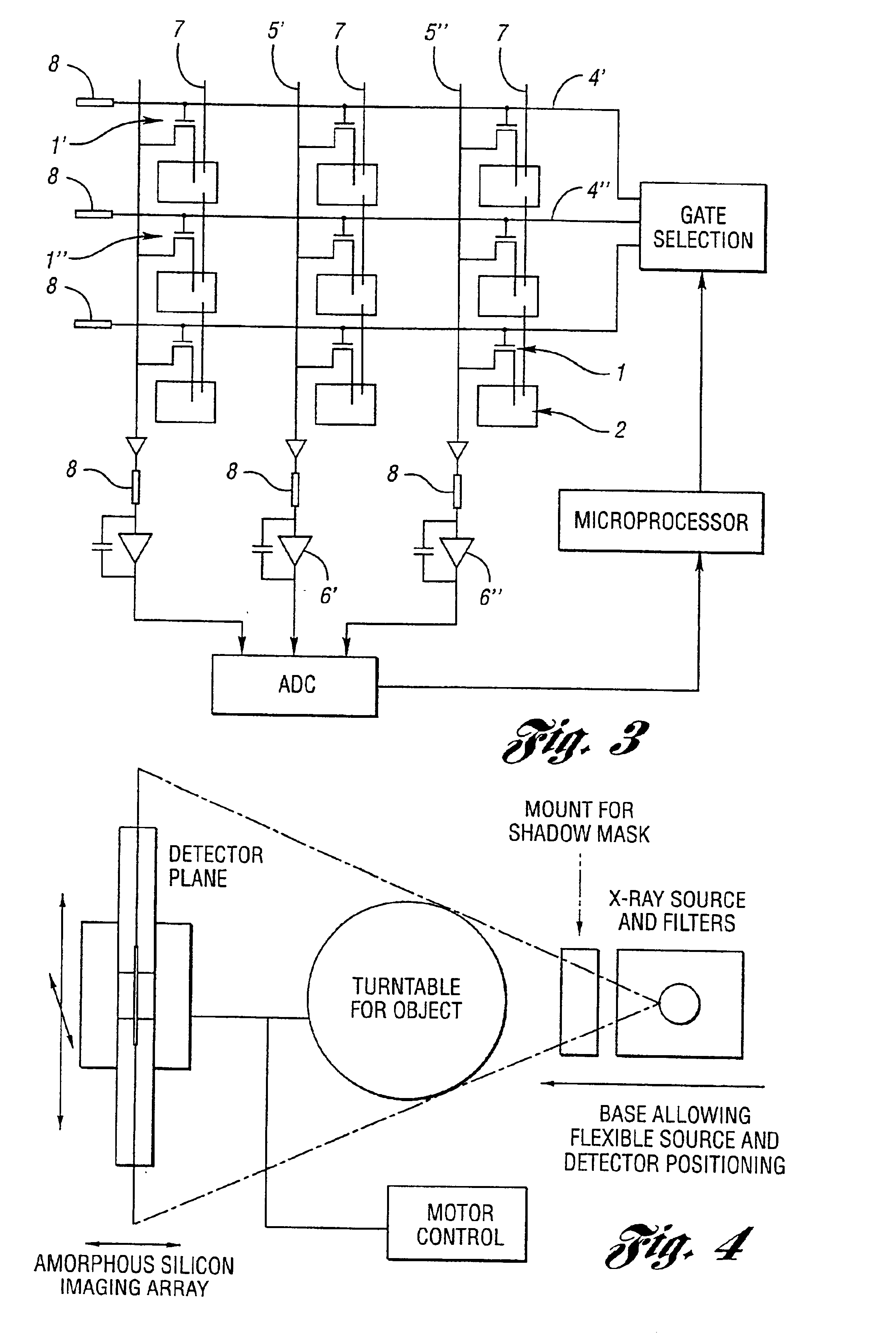
1. The pixel rows are grouped into clusters of two: two neighboring pixels, one from each row, are combined to form a new pixel. The two pixels share the same DATA line (for example 1′ and 1″ in FIG. 3). The exposure of one of the two pixels (for example 1′) is set to a low value, while the exposure of the other pixel (1″) is set to a high value. The e...


PUM


Abstract

A method, processor and computed tomography (CT) machine for generating images utilizing high and low sensitivity data collected from a flat panel detector having an extended dynamic range. Hardware modifications for extending the dynamic range include grouping pixel rows and pixel columns into clusters of two. The sensitivity of the rows / columns is modified by positioning optical masks that have different transparencies for different rows / columns. Software modifications for extending the dynamic range include taking two correlated exposure scan measurements at each angle and combining the two data sets into one scan prior to image reconstruction. This method uses a spatially varying pixel exposure method where several adjacent pixels are clustered and each cluster has a different sensitivity. The signals of these clusters are combined to form one image effectively producing an increased dynamic range. The flat panel imager may be an a-Si:H based flat panel detector for use in X-ray imaging, including cone beam computer tomography (CBCT).

Description

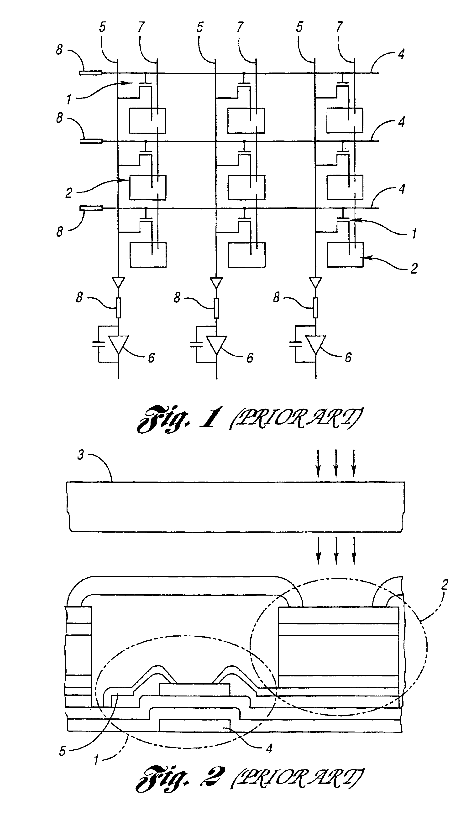
BACKGROUND OF THE INVENTION1. Field of the InventionThis invention relates to methods, processors and computed tomography (CT) machines for generating images utilizing high and low sensitivity data collected from a flat panel detector having an extended dynamic range.2. Background ArtReferring to FIGS. 1 and 2, flat panel imagers (also referred to as flat panel arrays or flat panel detectors) (i.e., FPIs) are large-area arrays with pixels consisting of a hydrogenated amorphous silicon (a-Si:H) thin-film transistor 1 (TFT) coupled to an a-Si:H photodiode sensor 2, as shown in U.S. Pat. No. 5,262,649.On top of the array is an X-ray converter 3 based on a phosphor material such as Gd2O2S:Tb or scintillating material such as CsI:(T1). When an X-ray photon reaches the X-ray converter 3 (also referred to as a screen), it stimulates the emission of light photons which are then detected by the reverse-biased photodiode sensor 2. The reverse bias, together with a large intrinsic region of th...

Claims


Application Information

Patent Timeline
IPC IPC(8): H04N5/32G01T1/29
CPCG01T1/2928H04N5/2355H04N5/32H04N23/741H04N23/30
Inventor CLINTHORNE, NEAL H.SUKOVIC, PREDRAG
Owner RGT UNIV OF MICHIGAN
Learn More