Eureka AIR delivers breakthrough ideas for toughest innovation challenges, trusted by R&D personnel around the world.

Power transmission belt

a transmission belt and power technology, applied in the field of power transmission belts, can solve problems such as insufficient abrasion resistan

Inactive Publication Date: 2005-03-15
MITSUBOSHI BELTING LTD
View PDF4 Cites 20 Cited by
  • Summary
  • Abstract
  • Description
  • Claims
  • Application Information

AI Technical Summary

Problems solved by technology

However, with the existing rubber and fiber technology conventionally used, and the severe operating conditions and environments in which power transmission belts are often required to perform, abrasion resistance may not be adequate, as a result of which premature belt failure may occur.

Method used


Image

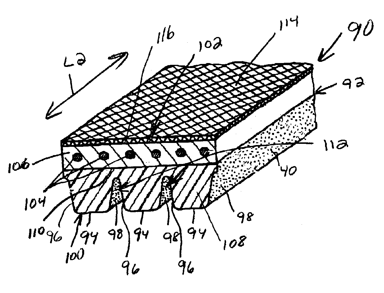
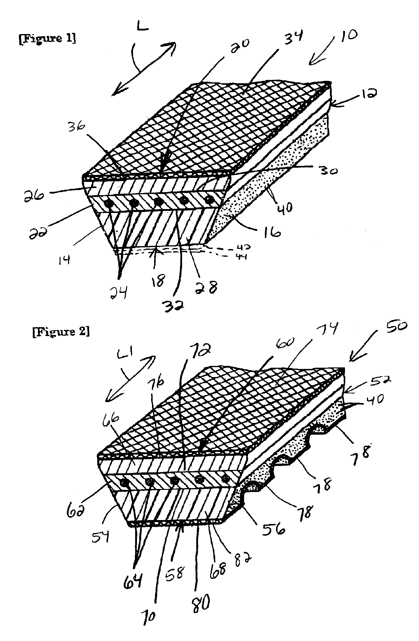
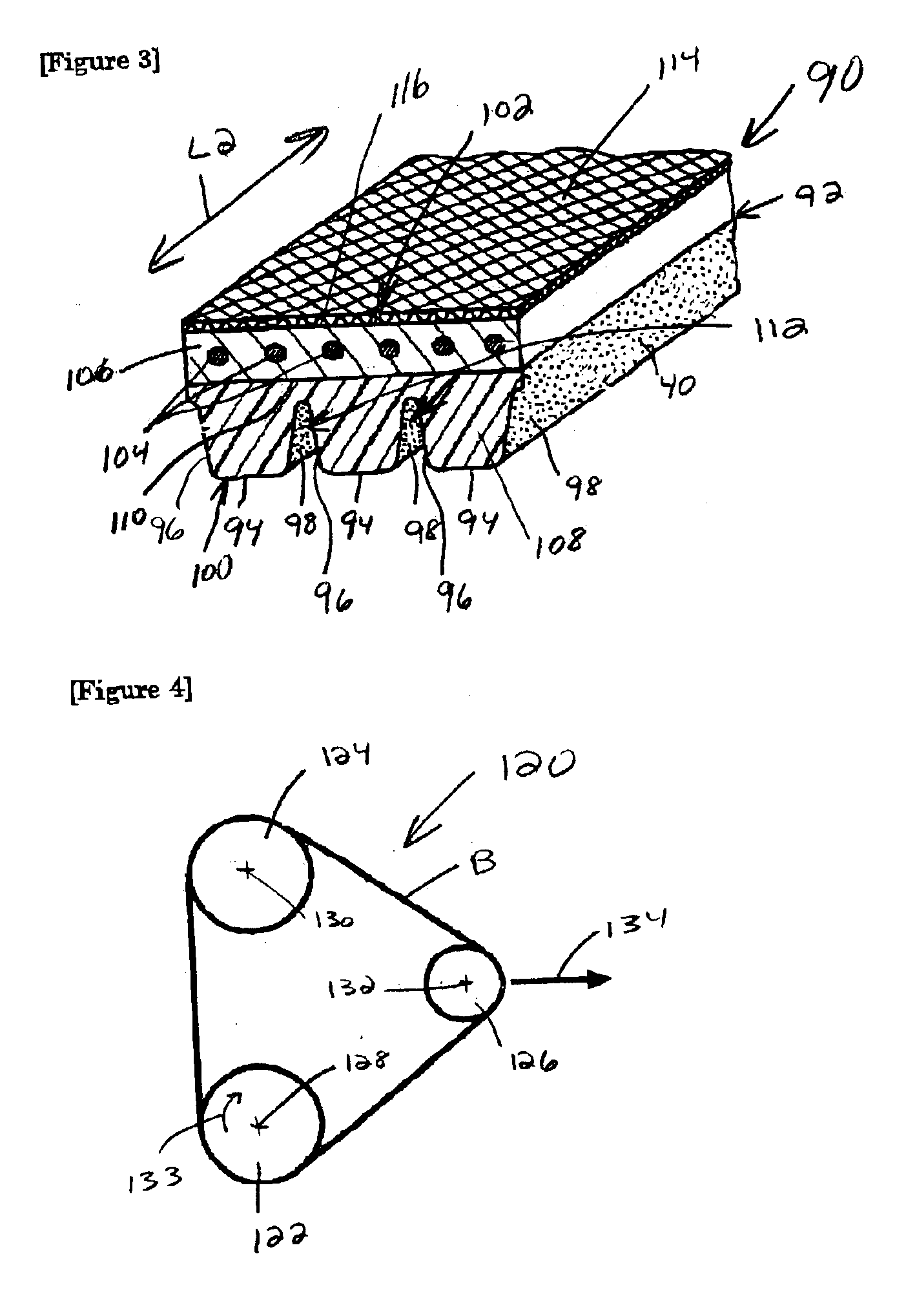
  • Power transmission belt
  • Power transmission belt
  • Power transmission belt

Examples


Embodiment Construction

and Comparative Examples 1-3 were prepared to carry out comparative testing.

Poly-p-phenylene benzobisoxazole fiber was made from a product manufactured by Toyobo, and sold commercially under the trademark ZYLON™. The ZYLON™ fiber was an HM grade material and cut to lengths of 3 mm. The fiber diameter was 1.7 dtex.

p-Aramid fibers were made from filaments manufactured by Teijin-Twaron, and sold commercially under the trademark TWARON™. Filaments, from which the fibers were cut, had a size of 1,670 dtex / 1,000 filaments. The fibers were dipped in an RFL solution, as shown in Table 1, below, and processed at 200° C. for one minute.

TABLE 1Compounded SubstancesParts by MassVinylpyridine latex (40%)244.0Resorcinol11.037% Formalin16.2Sodium hydroxide0.3Water299.5

The processed filaments were cut to produce fibers having a length of 3 mm and a diameter of 1.7 dtex. Rubber compositions, as shown in Table 1, were combined with the resulting short fibers.

TABLE 2ALL COMPONENTS IDENTIFIED IN MASS P...


PUM

PropertyMeasurementUnit
lengthaaaaaaaaaa
lengthsaaaaaaaaaa
lengthaaaaaaaaaa

Abstract

A power transmission belt having a body with a length, a width, an inside, and an outside. The body includes a rubber composition. The body further has a plurality of short fibers in the rubber composition. The plurality of short fibers may include a plurality of poly-p-phenylene benzobisoxazole fibers.

Description

BACKGROUND OF THE INVENTION1. Field of the InventionThis invention relates to power transmission belts and, more particularly, to a power transmission belt having a body with short fibers embedded therein.2. Background ArtIt is known to improve the abrasion resistance of power transmission belts, such as V-belts and V-ribbed belts, by adding short, reinforcing fibers to a rubber component defining at least a part of the belt. The fibers are typically added to a rubber layer in the compression section of the belt. As one example, a V-belt is disclosed in Japanese Patent No. 3,113,599 with a compression rubber layer having short nylon and Vinylon™ fibers embedded therein. Japanese Patent Document No. JP-B-5-63656 discloses a V-belt with short reinforcing aramid fibers embedded therein. Japanese Patent Document No. JP-B-7-81609 discloses a V-ribbed belt with a compression rubber layer having short nylon and aramid fibers embedded therein.It is well known that poly-p-phenylene benzobiso...

Claims


Application Information

Patent Timeline
Patent Type & Authority Patents(United States)
IPC IPC(8): F16G1/08F16G5/20F16G5/00F16G5/06F16G1/00
CPCF16G1/08F16G5/06F16G5/20Y10T428/2913Y10T428/298Y10T428/2918Y10T428/26Y10T428/2933Y10T428/2971Y10T428/249933Y10T428/249924
Inventor TAKEHARA, TAKESHIHASAKA, HITOSHIKIMURA, TAKESHIKUNIHIRO, YASUTSUGUTAKADA, TOSHIMICHI
Owner MITSUBOSHI BELTING LTD
Why Eureka
Eureka Blog
Learn More