
Apparatus and method for improving gas flow uniformity in a continuous stream ink jet printer

Inactive Publication Date: 2005-03-15
EASTMAN KODAK CO
View PDF17 Cites 117 Cited by
  • Summary
  • Abstract
  • Description
  • Claims
  • Application Information

AI Technical Summary

Benefits of technology

Therefore, the primary advantage of the present invention is in improving the quality of printing from of a continuous ink jet printhead by improving gas flow uniformity, so as to allow consistent control of the deflection of the droplets.
is in improving the quality of printing from of a continuous ink jet printhead by improving gas flow uniformity, so as to allow consistent control of the deflection of the droplets.
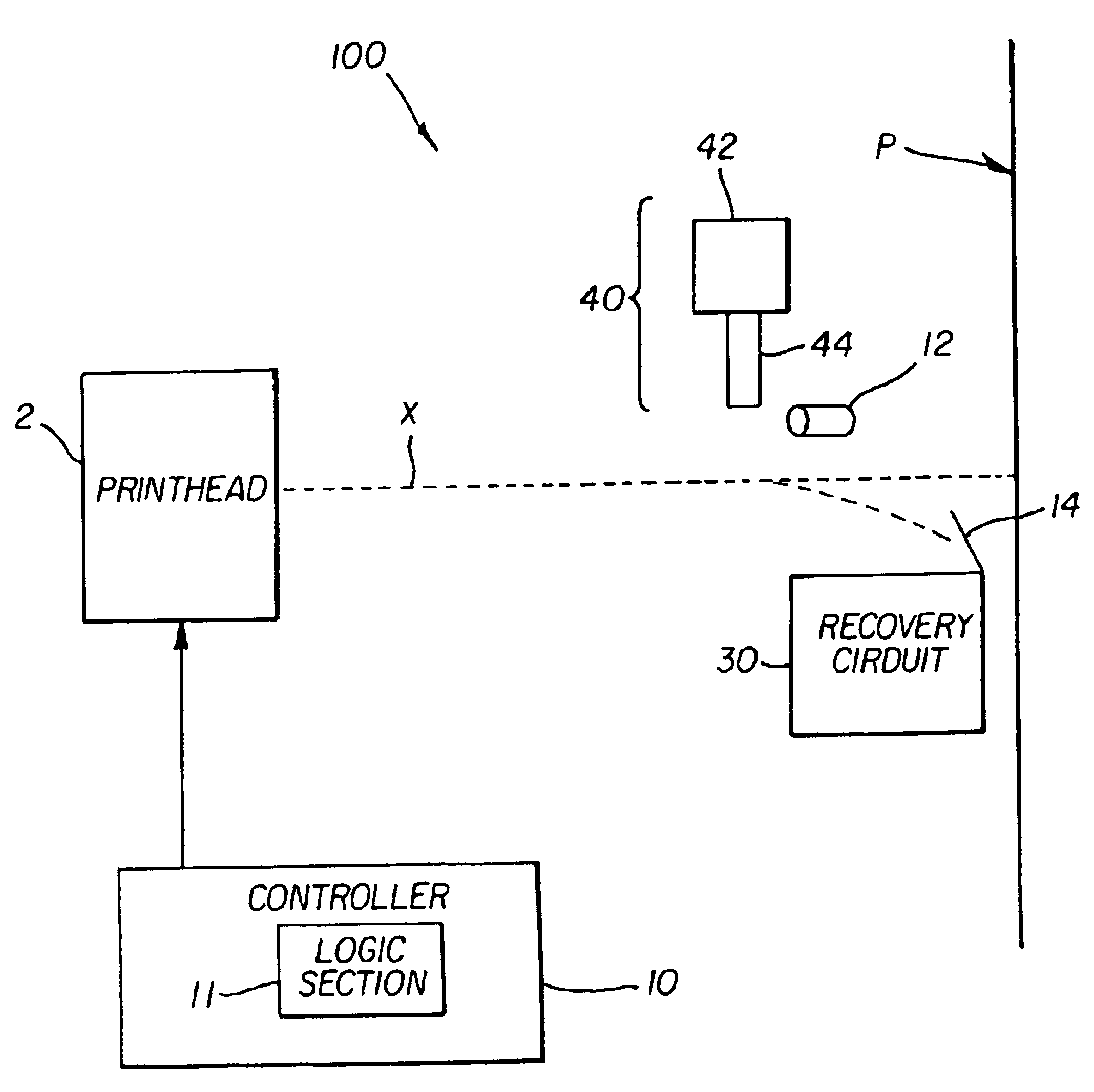
The above noted and other advantages are attained in accordance with one embodiment of the present invention by a method of enhancing print quality of a continuous ink jet printing device in which selected droplets in a stream of droplets are selectively deflected to impinge on a print medium including the steps of providing a stream of plurality of ink droplets, providing a gas flow that deflects the plurality of ink droplets, monitoring uniformity of the gas flow, and adjusting a flow characteristic of the gas flow based on the monitored uniformity of the gas flow.
The step of adjusting flow characteristic of the gas flow may be attained various ways, however, in the embodiments of the invention presented here, the step of adjusting flow characteristic of the gas flow is attained by increasing or decreasing flow rate of the gas flow. In one embodiment of the invention, at least one of a flow rate of the gas flow relative to a droplet stream is adjusted by varying a flow area of the gas outlet. In another embodiment, the step of adjusting flow characteristic of the gas flow is attained by generating an acoustic wave to oppose the gas flow. In still another embodiment, the step of adjusting flow characteristic of the gas flow is attained by actuating an adjustment mechanism that adjustably varies at least one of a flow rate of the gas flow and a flow area of the outlet while in another embodiment, the step of adjusting flow characteristic of the gas flow is attained by precision machining the outlet.
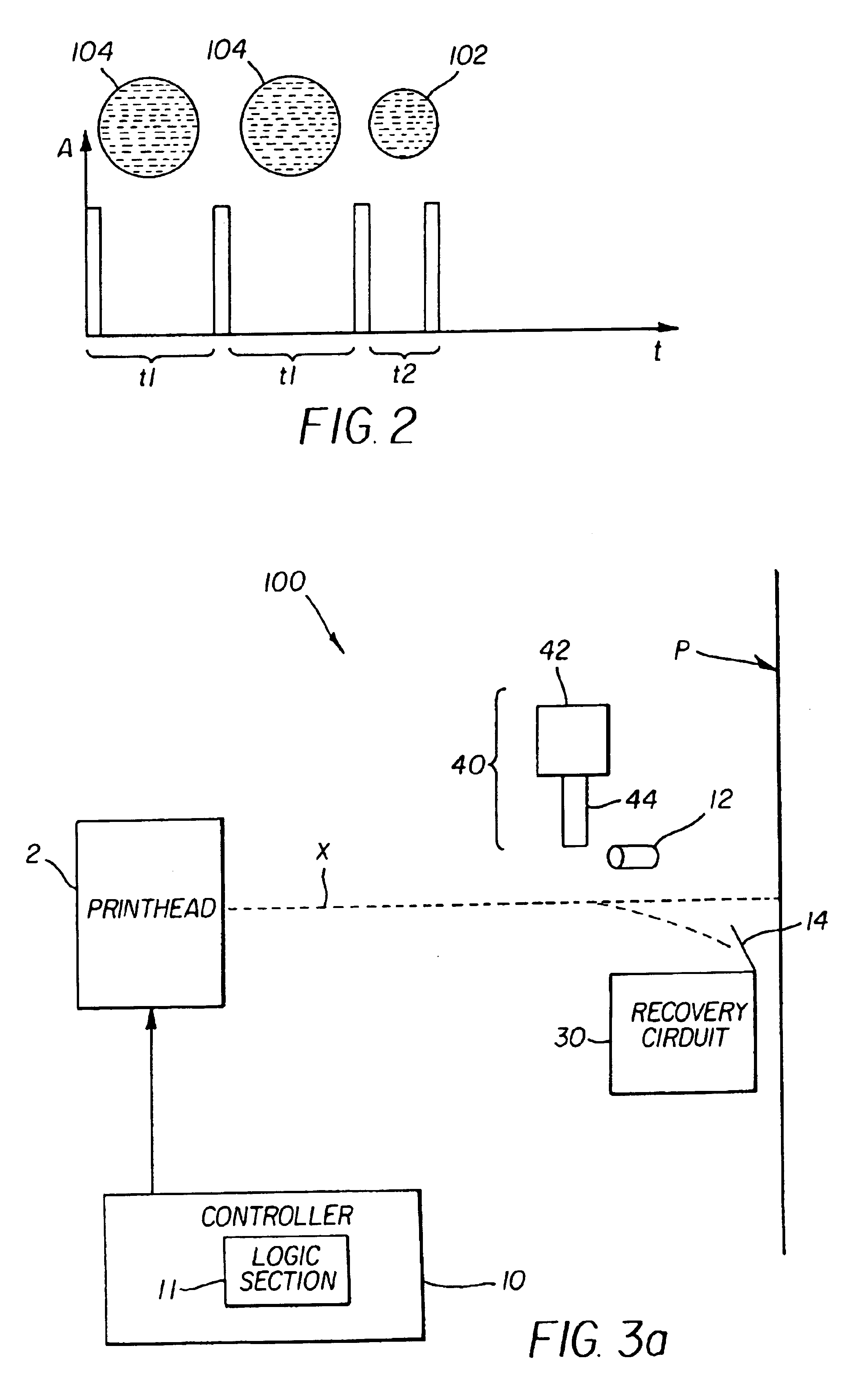
In accordance with the various embodiments of the present invention, the step of monitoring uniformity of gas flow is attained by a hot-wire sensor or by monitoring trajectory paths of the deflected plurality of ink droplets. In this regard, in such an embodiment, lack of variation in trajectory paths of the deflected plurality of ink droplets is indicative of uniform gas flow, and presence of variation in trajectory paths of the plurality of ink droplets is indicative of non-uniform gas flow. The trajectory paths of the deflected plurality of ink droplets may be monitored by providing a laser beam across the gas flow and monitoring trajectory paths of the plurality of ink droplets relative to the laser beam. Alternatively or in addition thereto, the step of monitoring trajectory paths of the deflected plurality of ink droplets may include impacting the deflected plurality of ink droplets on a print media and comparing location of the plurality of ink droplets on the print media.
In accordance with another aspect of the present invention, a continuous ink jet printing device is provided for printing an image in which selected droplets in a stream of droplets are selectively deflected to impinge on a print medium, the printing device including an ink droplet forming mechanism adapted to provide a stream of plurality of ink droplets, each ink droplet being substantially same size, a droplet deflector with an outlet, the droplet deflector being adapted to generate a gas flow provided through the outlet that deflects the plurality of ink droplets, a monitoring mechanism adapted to monitor uniformity of the gas flow from the droplet deflector, and an adjustment mechanism operatively coupled to the droplet deflector to adjust a flow characteristic of the gas flow based on the monitored uniformity of the gas flow.

Problems solved by technology

Otherwise, non-uniform air flow can cause improper deflection of the droplets at any given time causing droplet to droplet variation in the location of printing on the print medium thereby reducing the print quality.

Method used


Image

  • Apparatus and method for improving gas flow uniformity in a continuous stream ink jet printer
  • Apparatus and method for improving gas flow uniformity in a continuous stream ink jet printer
  • Apparatus and method for improving gas flow uniformity in a continuous stream ink jet printer

Examples


Embodiment Construction

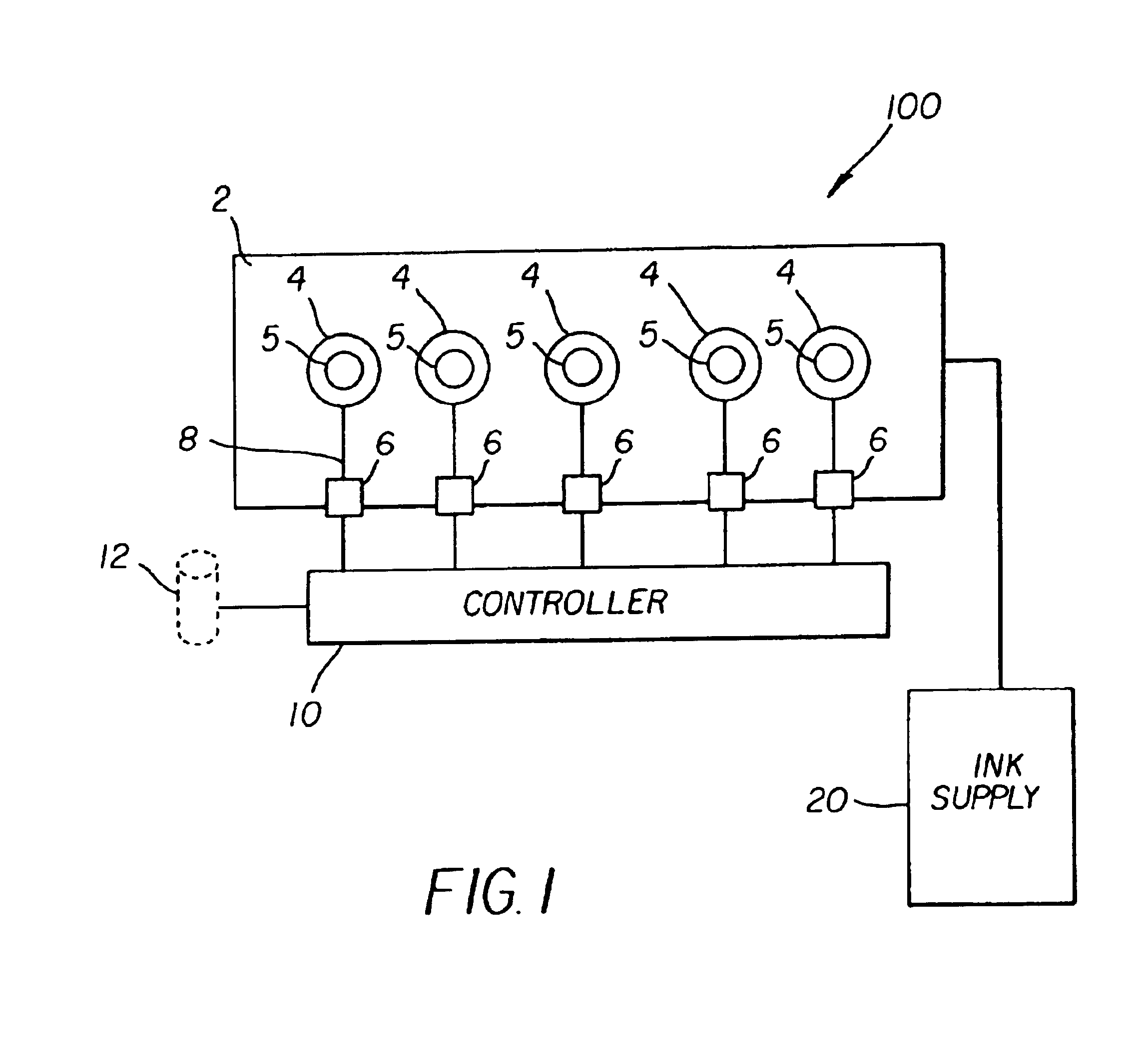
FIG. 1 illustrates a print head mechanism in accordance with a preferred embodiment of the invention. Mechanism 100 includes printhead 2, at least one ink supply 20, and controller 10. Although mechanism 100 is illustrated schematically and not to scale for the sake of clarity, one of ordinary skill in the art will be able to readily determine the specific size and interconnections of the elements. Printhead 2 can be formed from a semiconductor material, such as silicon, using known semiconductor fabrication techniques, such as complementary metal oxide semiconductor (CMOS) fabrication techniques and micro electro mechanical structure (MEMS) fabrication techniques, or from any materials using any known or future fabrication techniques and incorporates a thermal actuator.

Plural nozzles 5 are formed in printhead 2 to be in fluid communication with ink supply 20 through ink passages (not shown) also formed in printhead 2. Each ink supply 20 may contain a different color ink for color p...


PUM


Abstract

A method of enhancing print quality of a continuous ink jet printing device and such a printing device in which selected droplets in a stream of droplets are selectively deflected to impinge on a print medium, the method including the steps of providing a plurality of ink droplets, each printing ink-droplet being substantially same size, providing a gas flow that deflects the plurality of ink droplets, monitoring uniformity of the gas flow, and adjusting a flow characteristic of the gas flow based on the monitored uniformity. The step of adjusting flow characteristic of the gas flow is attained by changing flow rate of the gas flow or flow area of the outlet. In one embodiment, the step of monitoring uniformity of gas flow includes monitoring trajectory paths of the deflected plurality of ink droplets.

Description

FIELD OF THE INVENTIONThis invention relates generally to the field of printing devices, and in particular to improving the quality of print yielded from continuous stream ink jet printers in which a liquid ink stream is broken into droplets, some of which are selectively deflected by a gas stream.BACKGROUND OF THE INVENTIONTraditionally, digitally-controlled ink jet color printing is accomplished by one of two technologies. Both can utilize independent ink supplies for each of the colors of ink provided. Ink is fed through channels formed in the printhead and each channel includes a nozzle from which droplets of ink are selectively ejected and deposited upon a print medium, such as paper. Typically, each technology requires separate ink delivery systems for each ink color used in printing. Ordinarily, the three primary subtractive colors, i.e. cyan, yellow and magenta, are used because these colors can produce, in general, up to several million shades or color combinations.The firs...

Claims


Application Information

Patent Timeline
IPC IPC(8): B41J2/07B41J2/03B41J2/015B41J2/09B41J2/105B41J2/075
CPCB41J2/03B41J2/09B41J2/105B41J2202/16B41J2002/031B41J2002/033
Inventor JEANMAIRE, DAVID L.
Owner EASTMAN KODAK CO
Learn More